Reviewing Aerotriangulation (AT) and Reconstruction Tiles
Upon completion of aerotriangulation or any of the build steps, the aerotriangulation/reconstruction tiles can be previewed in the 3D Window, with the tiles colorized according to their processing status. Additional tile information (tile camera positions and build data) can be viewed from the Tile tab.
The sections that follow describe the activities that can be performed to evaluate the aerotriangulation/reconstruction tile results:
§ View aerotriangulation tiles
§ Display original camera positions for tiles
§ Display calculated camera positions for tiles
§ View an aerotriangulation tile’s sparse point cloud
§ Display reconstruction tile results
§ Set a reconstruction tile's display style
§ View a tile’s production report
§ View an aerotriangulation tile’s quality report
Viewing Aerotriangulation (AT) Tiles
To view aerotriangulation tiles:
Note: This information is also available in the AT Tiles list. See "Selecting Tiles" and "Viewing Tile Information in the Tile List" in this chapter for information.
1. In the Project Tree, select the AT Tiles check box. The aerotriangulation tiles are displayed in the 3D Window, colorized according to their aerotriangulation status:
§ White tile – Unprocessed
§ Purple tile – Aerotriangulation completed
§ Yellow tile – Aerotriangulation merged
§ Orange border – Aerotriangulation failed (retrying)
§ Red border – Aerotriangulation failed
§ Blue border - <80% Success
Note: In the AT Tiles legend, the colored squares (e.g. ![]() ) indicate colored tiles, while the colored lines (e.g.
) indicate colored tiles, while the colored lines (e.g. ![]() ) indicate a colored border.
) indicate a colored border.
2. If you hover anywhere on the tile, the tile's name and number of photos in the tile are displayed at the top left corner of the 3D Window.
3. In the 3D Window, click the tile you want to review, or select the tile in the Tiles List. The Tile tab is displayed from which you can navigate to the tile, display its original and calculated camera positions and sparse point cloud, and view quality reports. See "Navigating to a Tile", "Displaying Original Camera Positions for Tiles", "Displaying Calculated Camera Positions for Tiles", "Viewing an Aerotriangulation Tile’s Sparse Point Cloud", "Viewing a Quality Report" and "Viewing a Production Report" in this chapter for information.
Viewing Reconstruction Tiles
To view the reconstruction tiles:
Note: This information is also available in the Reconstruction Tiles list. See "Selecting Tiles" and "Viewing Tile Information in the Tile List" in this chapter for information.
1. In the Project Tree, select the Reconstruction Tiles check box. The reconstruction tiles are displayed in the 3D Window, colorized according to the last build processing step completed for the tile.
§ Yellow tile – Aerotriangulation is complete.
§ Pink tile – All steps through point cloud creation are complete.
§ Dark Blue tile – All steps through model creation are complete,
§ Light Blue tile – All steps through model texturing are complete.
§ Green tile – All steps through project output are complete.
§ Orange border – An error occurred in the processing step that follows the last successfully completed step and a retry mechanism will be applied soon (e.g., if a dark blue colored tile has an orange border, this indicates that the 3D model creation step completed successfully but that model texturing failed and will be retried).
§ Red border – Tile failed.
§ Dark Red border – Insufficient photo coverage for reconstruction.
Note: In the Reconstruction Tiles legend, the colored squares (e.g. ![]() ) indicate colored tiles, while the colored lines (e.g.
) indicate colored tiles, while the colored lines (e.g. ![]() ) indicate a colored border.
) indicate a colored border.
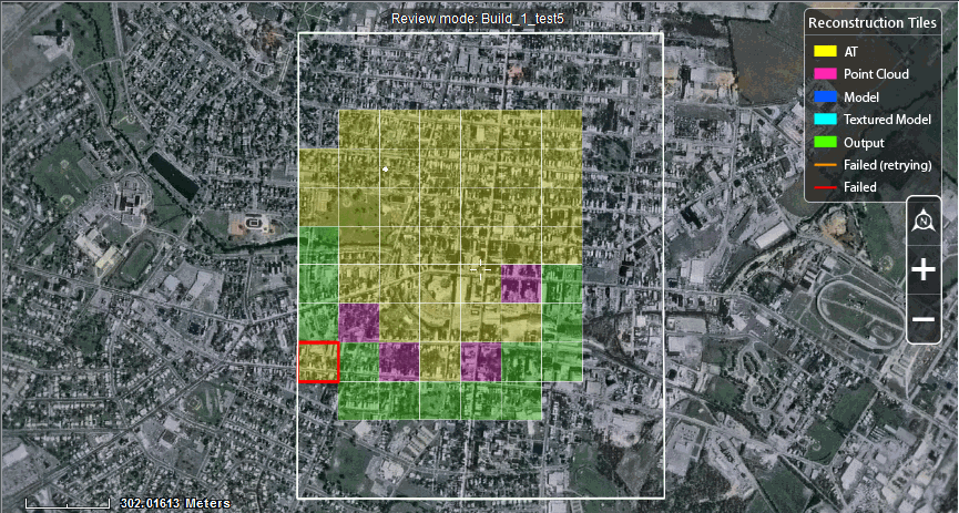
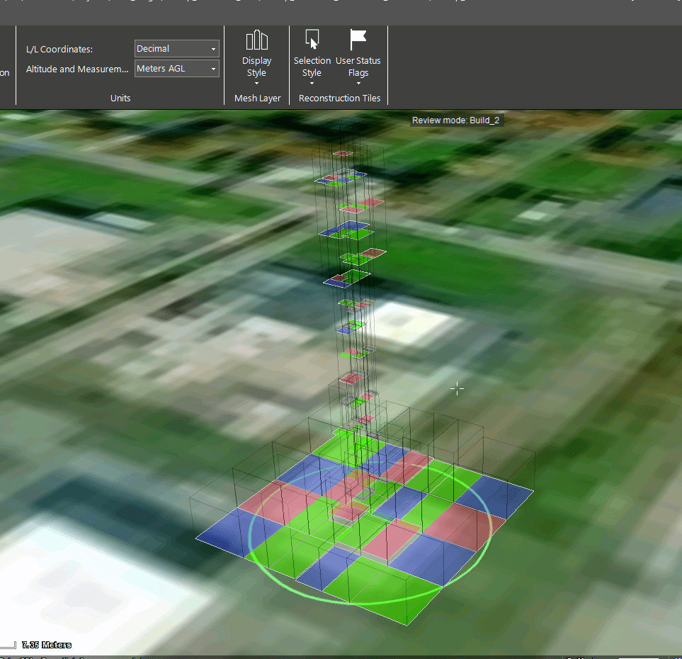
Reconstruction Tiles
2. If you hover anywhere on the tile, the tile's name and number of photos in the tile are displayed at the top left corner of the 3D Window.
3. In the 3D Window, click the tile you want to preview, or select the tile in the Reconstruction Tiles list. The Tile tab is displayed from which you can navigate to the tile, display its original and calculated camera positions and reconstruction tile results, view production reports, and export and import the tile’s model. See "Navigating to a Tile", "Displaying Original Camera Positions for Tiles", "Displaying Calculated Camera Positions for Tiles", "Displaying Reconstruction Tile Results", and "Viewing a Production Report" in this chapter and the "Importing and Exporting Models" chapter for information.
Selecting Tiles
Tiles can be selected either in the 3D Window or from the AT or Reconstruction Tiles Lists to perform various commands on them, e.g., jump to tile, show calculated information, or show AT or reconstruction tile results.
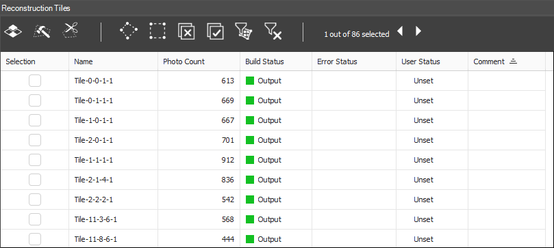
Reconstruction Tiles List
To select tiles:
1. In the Project Tree, select the Reconstruction Tiles or AT Tiles group.
2. In the 3D Window, click the tile you want to select, or select the tile(s) in the Reconstruction Tiles orAT Tiles list. You can multi-select tiles using the Tile List commands.
Note: If you turned on global selection, you can select a tile in the 3D Window even without first selecting the Tiles group in the Project Tree as long as the tiles are visible in the 3D Window.
See "Showing and Hiding Group Items" and "Selecting Items Using the Item List" in the "Using the Project Tree and Item List" chapter and "Selecting Objects in the 3D Window" in the "Basic Concepts" chapter for information.
3. If you want to save your selection, right-click in the Reconstruction Tiles orAT Tiles list, and select Save Selection.
4. To clear your selection, right-click, and select Clear Selection.
5. To load a tile's .select file with selection information, right-click, and select Load Selection. See "Tile Menu" in the "Using the Project Tree and Item List" chapter for more information.
Viewing Tile Information in the Tile List
The AT and reconstruction tiles lists provide information about each tile, including: photo count, build processing status, and error status. See "Selecting Items Using the Item List" in the "Using the Project Tree and Item List" chapter for more information.
To view tile information:
§ In the Project Tree, select the AT Tiles or Reconstruction Tiles group. The tile list displays all the tiles in the selected group, and the following information:
|
Property |
Description |
|
Selection |
Select the check box to select the tile in the 3D Window. You can select multiple tiles to perform actions on multiple tiles. |
|
Name |
Name of the tile (Read-only). |
|
Photo Count |
Number of photos in the tile (Read -only). |
|
Photos Calculated |
Number of photos in AT tile for which PhotoMesh successfully calculated camera position (only AT) (Read -only). |
|
Calculated % |
Percentage of photos in AT tile for which position information was calculated: Photos Calculated/Photo Count (only AT) (Read -only). |
|
Build Status |
For AT tiles: § Unprocessed § AT completed § AT merged For reconstruction tiles: § Initiated § Point Cloud § Model § Textured Model § Output (Read -only) Note: The tiles in the 3D Window are also colorized based on build status. See "Viewing Aerotriangulation (AT) Tiles" and "Viewing Reconstruction Tiles" in this chapter for information. |
|
Error Status |
Indicates if there was an error in creating the tile: Failed, Failed (retrying), No coverage (only reconstruction) or <80% success (only AT) (Read -only). |
|
User Status |
Click the dropdown arrow, and select the applicable status, indicating what actions still need to be performed on the tile, e.g., rebuild, editing or external retouch. You can also set the user status from the Tile tab > User Status. User status flags can be displayed in the 3D Window on each of the tiles to indicate at a glance the current status of each tile. See "Setting and Displaying User Status Flags and Legend" in this chapter for information. You can customize the name and color associated with each user status in the Options menu. See "Setting PhotoMesh Options" in the "Basic Concepts" chapter for more information. § For AT Tiles: OK, Requires Rebuild, Requires GCP. § For Reconstruction Tiles: OK, Requires Rebuild, Requires Editing, Requires External Retouch. Note: User status can also be set from the Tiles tab (Tiles tab > User Status). |
|
Comments |
Free text field where you can add any applicable information about the tile. You can add comments from the Tile tab > User Status. |
Navigating to a Tile
To fly or jump to a tile:
1. Select the required tile. See "Selecting Tiles" in the "Reviewing Your Build" chapter.
Note: If multiple tiles are selected, navigation is to the last selected tile.
2. On the Tile tab, in the View group, click Fly to Tile/ Jump To Tile.
Displaying Original Camera Positions for Tiles
After the aerotriangulation step has begun, you can display photos’ original camera positions.
To display photos in the original camera positions defined in the project:
1. Select the required tile. See "Selecting Tiles" in this chapter. The Tile tab is displayed.
2. On the Tile tab, in the Original Photos group, toggle on Original.
3. On the Tile tab, in the Original Photos group, in the Color Code dropdown, select one of the following options for color coding of the photos’ camera symbols:
§ Status – Camera symbols are color coded based on photo status (calculated/ not calculated).
§ Collection – Camera symbols are color coded according to collection, with a random color assigned to each collection’s camera symbol.
Note: These settings can also be accessed from the View tab.
Displaying Calculated Camera Positions for Tiles
Calculated camera positions for photos can only be displayed after the aerotriangulation step is complete.
Note: When calculated camera positions are displayed, you can also view calculated property information in the photo list. See "Calculated Camera Position Properties" in the "Photo Management" chapter for information.
To display photos in the camera positions calculated through aerotriangulation:
1. Select the required tile. See "Selecting Tiles" in this chapter. The Tile tab is displayed.
2. On the Tile tab, in the Calculated Photos group, toggle on Calculated. In the 3D Window, the photos are displayed in the camera positions calculated through aerotriangulation, and calculated positioning information is included in the photo list. See "Photo List" in the "Photo Management" chapter for information.
3. On the Tile tab, in the Calculated Photos group, in the Color Code dropdown, select one of the following options for color coding of the photos’ camera symbols in the 3D Window:
§ Status – Camera symbols are color coded based on status (calculated/ not calculated).
§ Collection – Camera symbols are color coded according to collection, with a random color assigned to each collection’s camera symbol.
§ Median Error – Camera symbols are color coded according to median error (px):
· Green: px < 0.5
· Orange: 0.5 < px < 1
· Purple: px > 1
§ Reconstruction Group – Camera symbols are color coded according to reconstruction group (i.e., photo blocks created in the AT process), with a random color assigned to each reconstruction group’s camera symbol. This information is significant in identifying the largest group (i.e., the group PhotoMesh will perform reconstruction on) and determining which additional photos can be connected to this group using tie points and other methods, for optimal output.
§ Number of Matches - Camera symbols are color coded according to the number of photo matches:
· Red: matches <= 2
· Orange: 2< matches <= 4
· Green: matches > 4
Viewing an Aerotriangulation Tile’s Sparse Point Cloud
A sparse point cloud is a representation of all photo features that were automatically found in two or more project photos, with their computed positions.
To view an AT tile’s sparse point cloud:
1. Select the required tile. See "Selecting Tiles" in this chapter. The Tile tab is displayed.
2. On the Tile tab, in the Sparse Point Cloud group, click Show Point Cloud.
Note: The sparse point cloud may take some time to display the first time it is shown or after making changes to the project.
3. Select the Point Size in pixels.
4. Select the color coding option for classifying the point cloud’s points:
§ Single color – A single color is used for all points.
§ Num. tied photos – Points are color coded according to the number of photos in which this point was found.
· Orange – Two matches
· Green – Three or more matches
Displaying Reconstruction Tile Results
To display point cloud, 3D model, or texture results for a tile:
1. Select the required tile. See "Selecting Tiles" in this chapter. The Tile tab is displayed.
2. On the Tile tab, in the Show group, toggle on any of the following options:
§ Point Cloud – Click the arrow to select the data to display:
· Merged – Show point cloud created by supplementing LiDAR with points generated from photos where LiDAR information is insufficient.
· From Photos – Show point cloud created only from points generated from photos.
· From Lidars – Show point cloud created only from LiDAR points.
§ Model – Shows only the mesh model
§ Textured Model
§ Orthophoto – If RGB color bands were selected for the orthophoto, they are displayed. Otherwise, only the first band is displayed in grayscale mode. See "Selecting the Collections and Bands to Include in the Build Outputs" in this chapter for information.
Note: Each of these options is enabled only if the build step for this data was completed.
Setting and Displaying User Status Flags and Legend
You can set and display the user status of AT and reconstruction tiles. By default the user status options are used to indicate what actions still need to be performed on the tile, e.g., rebuild, editing or external retouch, but they can be customized as required from the Options menu. After setting user status, flags can be displayed in the 3D Window on each of the tiles to indicate at a glance the current status of each tile.
To set and display user status flags:
1. In the Project Tree, select the AT Tiles or Reconstruction Tiles group. The tile list displays all the tiles in the selected group.
2. Select the row of the required tile, and in the User Status column, click the dropdown arrow, and select the applicable status, indicating what actions still need to be performed on the tile, e.g., rebuild, editing or external retouch. You can also set the user status by selecting the tile and then selecting the status from the Tile tab > User Status. See "Viewing Tile Information in the Tile List" in this chapter for more information.
Note: You can customize the color and name associated with each user status in the Options menu. See "Setting PhotoMesh Options" in the "Basic Concepts" chapter for more information.
3. On the View tab, in the Reconstruction Tiles group, click the arrow under User Status Flags, and select Show User Status Flags.
4. If you want to show a user status legend that indicates what AT and reconstruction tile user status is associated with each color flag, on the same tab, click the arrow under User Status Flags, and select Show User Status Legend.
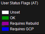
User Status Legend
Setting a Reconstruction Tile’s Display Style
There are four options for the display style of selected reconstruction tiles:
§ 2D Rectangle
§ 3D Box
§ 3D Box Fill
§ 3D Dynamic
Only the first three options are available when creating reconstruction tiles using a fixed 2D grid. When reconstruction tiles are created as adaptive 3D boxes, the display style option is automatically set to "3D Dynamic". This option is not available for 2D grid tiles. See "Setting Advanced Reconstruction Parameters" in the "Building" chapter for more information. In "3D Dynamic" mode, the tiles and their boxes are displayed in their absolute heights. Tiles that were created one on top of each other will appear as if they are floating in this mode.

To set the display style for selected reconstruction tiles:
§ On the View tab, in the Reconstruction Tiles group, click the arrow under Selection Style and select the style you want. If you want to display a frame around reconstruction tiles only when selecting a tile, and not when hovering over it, click the arrow under Selection Style and select Hide Tiles Hover.
To toggle the display of the tile bases of a reconstruction area that is divided into 3D tiles in an adaptive manner:
1. Select the required tile. See "Selecting Tiles" in the "Reviewing Your Build" chapter.
2. In the AT Tiles list or Reconstruction Tiles list, select the required tile(s), and toggle the Tile Base button ![]() on/off. The color of the base corresponds to the last build processing step completed for that tile. See "Viewing Reconstruction Tiles" in this chapter for more information. See "Setting Advanced Reconstruction Parameters" in the "Building" chapter for more information on adaptive 3D boxes.
on/off. The color of the base corresponds to the last build processing step completed for that tile. See "Viewing Reconstruction Tiles" in this chapter for more information. See "Setting Advanced Reconstruction Parameters" in the "Building" chapter for more information on adaptive 3D boxes.
Viewing a Production Report
The Production report contains statistical and graphical information about the build process. The first section of the report displays summary information: If the report is generated for a specific tile, it will only display information for that tile.
§ Basic project information including: project name, number of photos, and total input gigapixels.
§ Basic aerotriangulation information including: AT area, number of aerotriangulation tiles, calculated photos, and mean median error. The mean median error is the average of the median reprojection errors for all photos in the collection.
§ Basic reconstruction information including: output area, number of reconstruction tiles, and output coordinate system.
§ Performance information including: build and fuser time.
This summary section is followed on each report tab by detailed information and graphs relating to the respective tab:
§ (Build Process) Steps – Details about each build step: steps involved, tiles produced, processing time, and active fusers. When a reconstruction tile is selected, details display about the tile building steps (point cloud, model, texturing). When an aerotriangulation tile is selected, details display about the aerotriangulation.
§ Fusers – Statistics for each fuser regarding processing time for each build step and each tile in each step.
To view a production report:
1. Do any of the following:
Note: The same production report opens in each of these options but with different filter values selected.
§ On the Home tab, in the Process group, click the arrow under Reports, and select Production Report.
§ Select a tile in the 3D Window or in the tile list, and then on the Tile tab, in the View group, click the arrow under Reports, and select Tile Production Report. The report displayed will display information only for the selected tile.
§ In PhotoMesh Build Manager, click the Production Report button.
§ In PhotoMesh Build Manager, right-click a fuser, and select Fuser build report. The report displayed will display information only for the selected fuser.
§ In PhotoMesh Build Manager, right-click a tile, and select Tile build report. The report displayed will display information only for the selected tile.
2. At the top of the Production Report, select a report type. This determines what detailed information and graphs display in the section following the summary section.
§ Steps (Build)
§ Fusers
3. The detailed information and graph data can be filtered to display information only about tiles with warnings or errors or about specific build process steps, fusers, or aerotriangulation tiles. Click Filter and, select one of the following:
§ All
§ With warnings
§ With errors
§ User selection
4. If you choose User selection, the Select dialog is displayed:
a. Select the required step or fuser (depending on the report type being viewed). Use CTRL and SHIFT to multi-select. Then click OK.
b. If you want to change your selection, click Select to reopen the Select dialog.
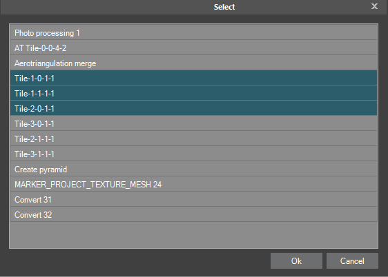
Select Dialog
5. If you want to expand or collapse parts of the report to make it easier to find and view only the information you want, click Expand/Collapse All at the top of the report.
6. If you want to export the Production Report as an HTML file, at the top of the report, click Export. Then in the Export Production Report dialog, browse to the required file location, and click Save.
7. If you want to print the report, at the top of the report, click Print.
Viewing a Quality Report
The Quality Report contains statistical and graphical information about the quality of the build and its aerotriangulation and reconstruction results. It highlights key information and alerts you to potential problems such as missing information, triangulation errors, or failed tiles, which are likely to affect the quality of your build output. This enables you to address and resolve the necessary issues. If the report is generated for a specific tile, it will only display information for that tile. The report contains the following sections:
§ Report Summary – Quick overview of the status of your build and warnings about errors or missing information that may need adjustment to produce a quality build.
§ Project Information – Basic project information including: project name, number of photos, and total input gigapixels.
§ Photos and Collections – Information about the photos in each collection including: number of photos, focal length, distortion and coordinate system
§ Control Points – Basic ground control point, check point, and tie point information including: triangulation error and sampled photos.
§ Reconstruction – Basic reconstruction information including: reconstruction area, number of reconstruction tiles, number of fusers, and total processing time.
§ Aerotriangulation Results – Basic aerotriangulation information including: number of aerotriangulation tiles, calculated photos, and mean median error. Aerotriangulation information for each tile is also provided: original and calculated distortion values, error, and principal point, control point information, and maps that graphically depict information about photo matches, level of detail, position accuracy and more. Each map has three views: from the top, front, and left.
To view a Quality Report, do either of the following:
§ On the Home tab, in the Process group, click the arrow under Reports, and select Quality Report. A PDF is created in the project build's Report folder.
§ Select the required tile. See "Selecting Tiles" in this chapter. Then on the Tile tab, in the View group, click the arrow under Reports, and select Quality Report. The report displayed will display information only for the selected tile.
Quality Report Error Messages
The Quality Report includes error messages to help you easily identify what are the causes of inadequate output results, so that you can make the necessary corrections before rebuilding.
Below are listed the most common error messages and some recommendations on how to handle them:
§ Input: Photos and Collections
Input: Photos and Collections
|
Field |
Message |
Recommendation |
|
Number of Photos |
Fewer than 20 photos in collection. / Fewer than 6 photos in collection. |
Check whether a collection was mistakenly split into two collections, and if so, merge the split groups into a single one. Homogeneous groups of photographs, all taken by the same physical camera with identical focal length and dimensions can be placed in the same collection. |
|
Image Width |
Missing property value. / Invalid property value. Value must be greater than 0. |
This information can usually be obtained from your data provider or camera manufacturer, and then entered in the collection property sheet or Excel/XML photo list file. |
|
Image Height |
Missing property value. / Invalid property value. Value must be greater than 0. |
This information can usually be obtained from your data provider or camera manufacturer, and then entered in the collection property sheet or Excel/XML photo list file. |
|
Sensor Width |
Missing property value. This property is necessary in calculating focal length. |
This information can usually be obtained from your data provider or camera manufacturer, and then entered in the collection property sheet or Excel/XML photo list file. If you don’t have access to this property value, focal length can instead be set based on the pixel size and focal length values or the focal length 35 value. |
|
Pixel Size |
Missing property value. This property is necessary in calculating focal length. |
This information can usually be obtained from your data provider or camera manufacturer, and then entered in the collection property sheet or Excel/XML photo list file. If you don’t have access to this property value, focal length can instead be set based on the sensor width and focal length values or the focal length 35 value. |
|
Focal Length |
Missing property value. / Invalid property value. Value must be greater than 0. |
This information can usually be obtained from your data provider or camera manufacturer, and then entered in the collection property sheet or Excel/XML photo list file. If you don’t have access to this property value, focal length can instead be set based on the focal length 35 value. |
|
Focal Length 35 |
Missing property value. This property is necessary in calculating focal length. / Invalid property value. Value must be greater than 0. |
This information can usually be obtained from your data provider or camera manufacturer, and then entered in the collection property sheet or Excel/XML photo list file. If you don’t have access to this value, focal length can instead be set based on focal length together with either pixel size or sensor width. If none of the required values are available, set focal length 35 to the default value of 50. |
|
Principal Point (X,Y) |
Principal point is too far from photo center. |
Verify that the principal point reference’s correct origin and units were selected in the collection property sheet or Excel/XML photo list file. |
|
Input Coordinate System |
Missing collection’s coordinate system information. / Invalid coordinate system information. |
If the XY values seem to be in degrees, i.e., they are in the range from -180 to 180 with 5-6 decimal places, the coordinate system is most likely WGS84 with EGM96 vertical datum. Enter this information in the collection property sheet or Excel/XML photo list file. |
|
Vertical Datum |
The WKT of one of your project coordinate systems references a vertical datum (GTX) file that was not found on your computer. |
Download the required GTX file. See here for more information. |
|
Name of Photo Collection - Photo Position Data |
Missing XYZ position data. |
Check if this information is available in an external positions file. If not, you can estimate the missing values by using the values of the adjacent photos, and enter this information in the photo property sheet. |
|
|
All of the project’s photos have the same XYZ values. |
Delete the position data from the property sheet. Verify if this information is available in an external positions file. |
|
|
Many of the project’s photos are positioned underground. |
Verify that the correct geoid/ellipsoid are set in the photo’s coordinates system. Also check that the correct altitude mode (relative/absolute) and offset are set in the collection property sheet. |
|
|
There are more than 10,000 photos in the project. |
Verify that PhotoMesh is running on a sufficiently powerful machine. PhotoMesh can process projects with more than 10,000 photos as long as the machine it is running on has sufficient compute, memory, and storage capabilities. |
|
Name of Photo Collection - Photo Orientation |
Invalid value. Orientation values must be in degrees. |
If values are in radians and photo information was imported in an Excel file, verify that the Omega/Phi/Kappa Units property is set to "Radians" in the Excel. Otherwise, If orientation values are in gon or radians, convert to degrees, and reimport the photos. |
|
Name of Photo Collection - Band Definition |
Mismatch between the number of bands according to the property sheet and the photo files’ metadata. |
Fix value in property sheet. |
Input: Lidar
|
Field |
Message |
Recommendation |
|
Coordinate System |
Missing Lidar’s coordinate system information. / Invalid coordinate system information. |
Verify the validity of the WKT in the coordinate system dialog. Fix as required. |
|
Location (bbox) |
Lidar point cloud points are all outside the AT or reconstruction area |
Verify in the Lidar List that the correct coordinate system and vertical datum are set. If a local coordinate system was set, it must be referenced to a known coordinate system. |
|
Content |
Lidar point cloud contains no points |
Verify the validity of the WKT in the coordinate system dialog and check that the projected point cloud falls in the expected area. You can also increase the Point Size for better visibility of the points and change Oversampling from Low to Best (right-click menu). |
Aerotriangulation Result
|
Field |
Message |
Recommendation |
|
Triangulation Error |
Triangulation error between 0.5px-1px. / Triangulation error > 1px |
Check the sensor parameters. Verify that radial/tangential distortion values are correct in property sheet or Excel/XML photo list file. |
|
Calculated Position |
Difference between photos’ calculated and inputted position values exceeds the error tolerance defined by the aerotriangulation Calculation Mode parameter. All of the project’s photos have the same calculated position. |
Verify that the control points were marked accurately and that photos’ inputted position and orientation information is correct. |
|
Focal Calculated |
Difference between photos’ calculated and inputted focal values exceeds the error tolerance defined by the Focal Length Accuracy parameter. / Difference between photos’ calculated and inputted focal values is greater than 50%. |
Check the input value. Fix if required and then rerun the AT. |
|
Principal point (X,Y) calculated |
Difference between photos’ calculated and inputted principal point values exceeds the error tolerance defined by the Principal Point Accuracy value. / Difference between photos’ calculated and inputted focal values exceeds permitted deviation. |
Check the input value. Fix if required and then rerun the AT. |
Control Points
|
Field |
Message |
Recommendation |
|
Number of GCPs |
Only 1 ground control point was added to collection. |
It is recommended to add at least 3-5 control points per AT tile, to enable them to be fully utilized in the AT process. When only two control points are provided, simple vertical adjustment, scaling and rotation are performed. When only one control point is provided, only vertical adjustment is performed. |
|
Number of Photos Marked |
Control points marked in 2 or fewer photos. / Control points marked in fewer than 2 photos. |
Mark each control point in at least three photos. |
|
Number of Photos Used |
Number of photos used is <= 2. |
Verify the accuracy of control point marking in the photos. |
|
Geographic Error Horizontal (X,Y) |
Per GCP: If greater than defined accuracy. / Per project: if >10% or GCPs have errors. |
Check that the coordinate system and vertical datum of both the control points and photos are accurate. |
|
Geographic Error Vertical |
Per GCP: If greater than defined accuracy. / Per project: if >10% or GCPs have errors. |
Check that the coordinate system and vertical datum of both the control points and photos are accurate. |
|
Geographic Error Circular |
Per GCP: If greater than defined accuracy. / Per project: if >10% or GCPs have errors. |
Check that the coordinate system and vertical datum of both the control points and photos are accurate. |
|
Triangulation Error RMS |
Root mean square (RMS) exceeds 0.5 pixels. |
Verify the accuracy of control point placement and their marking in photos. |
|
Triangulation Error Maximum |
Triangulation error exceeds 1 pixel. |
Verify the accuracy of control point placement and their marking in photos. |
Maps
Photo Matches Map
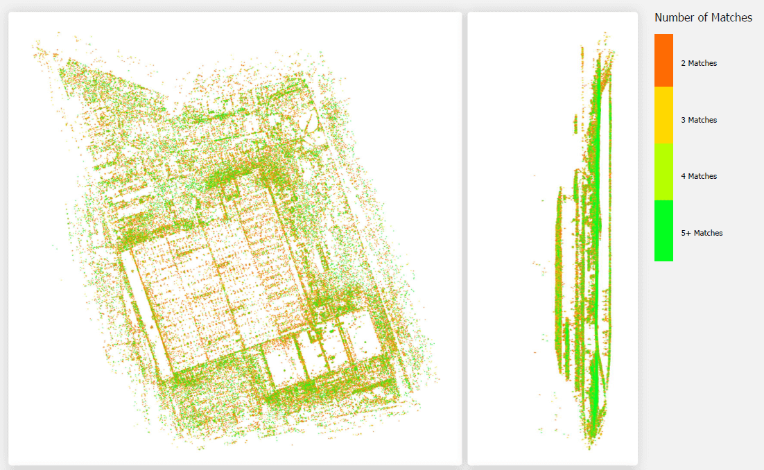
Color-coded map that graphically depicts the degree of photo overlap. Each match (feature that was found in at least two photos) in the defined AT area is colored according to the number of photos in which it was found.
§ Red – Minimal coverage (found in 2 photos)
§ Yellow – Moderate coverage (found in 3 photos)
§ Green – Strong coverage (found in 5 or more photos)
In oblique collections, moderate-strong coverage is generally necessary, but only in the area of interest, while on the project edges, minimal coverage will usually suffice. In nadir collections, minimal coverage even in the area of interest is generally sufficient. To improve matching in cases of weak coverage, it is recommended to use the AT: More Aggressive Match preset.
Connection and Projection Error Maps
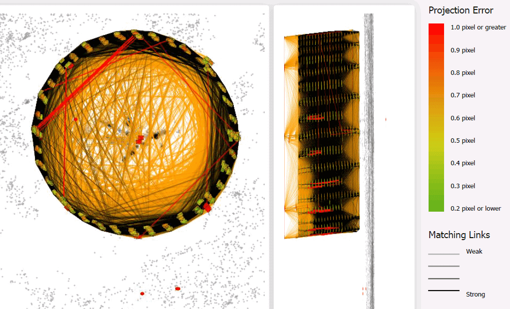
Projection error - Median of the triangulation errors of all the features in each photo. The triangulation error is the distance in pixels for every automatically identified feature, between its original position and the position computed through aerotriangulation. Each camera symbol is color coded, based on the level of projection error. If the projection error is greater than 0.6 pixels in a group of images localized in the project, it could be an indication of a bad control point, constraints in the camera model geometry, or an area with challenging features (forested areas with large time and/or shadow differences, or extremely urban areas with inconsistent coverage). It is recommended to review that area in the project AT in order to verify that there are no errors on the input data (control point or images), and that the images have proper overlap and coverage.
Connection - Lines connect between photos with common automatic tie points, with the weight of the connecting line corresponding to the number of common points. 3D automatic tie points are obtained by computing the positions of features (I.e., characteristic points on photos) that were automatically detected in two or more overlapping photos. If the links between photos are weak, manual tie points can be used to establish a stronger correspondence between project photos and improve aerotriangulation results. If the number of links remains low, the AT: More Aggressive Match preset can be applied when building the project to increase the likelihood of matches being made. The color of the connection lines provides information about the strength of the connection:
§ Black – Strong connections
§ Brown – Weak connections
§ Red – Initial connections that were later disconnected in the AT bundle adjustment process. This indicates that the overall connection in the area was not strong enough to maintain the link between the photos.
Ground Resolution Map
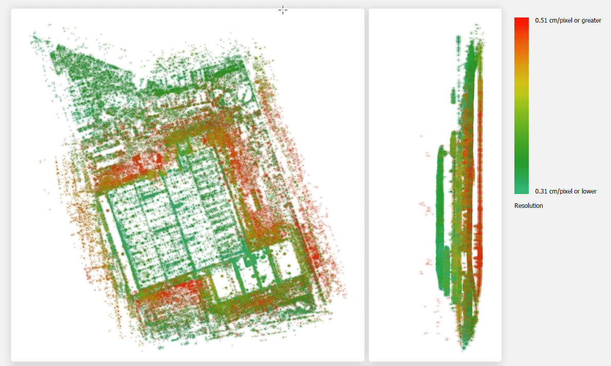
Color-coded map that provides information on the highest resolution that was achieved in cm per pixel for each 3D automatic tie point within the defined AT area. 3D automatic tie points are obtained by computing the positions of features (I.e., characteristic points on photos) that were automatically detected in two or more overlapping photos. Make sure that the expected resolution level is achieved in the area of interest. On the project’s edges, lower resolution will usually suffice.
Distance Map
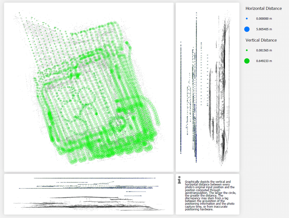
Graphically depicts the vertical and horizontal distance between every photo's original input position and the position computed through aerotriangulation. Each circle on the map represents a photo, with the size of the circle corresponding to the difference between the input values of the photo and its calculated values, i.e., the greater the difference, the larger the circle. The following are some of the distance map results you may see:
§ A consistent shift in length and direction from the input to computed values (depicted by lines), generally in large drone projects - This often indicates a lag between the acquisition of the positioning information and the photo capture time
§ A significant discrepancy between input and computed values in a specific stretch of the map, with minimal differences on either side. This may be caused by a consistent GPS offset between two different flights or by an incorrectly placed control point that has caused a significant shift in a specific section of the AT area.
§ Arc between original and calculated values may be because of tangential effect. This most commonly occurs with rolling shutter cameras, and low-quality lenses.
To improve positioning in cases of significant discrepancies between inputted and computed positions, it is recommended to use the AT: More Aggressive Matchpreset.
Exporting Photo List Information
Photo position and orientation properties can be exported to a CSV file. All columns currently displayed in the Photo list will be exported. See "Exporting Aerotriangulation Results" in this chapter for information on exporting your calculated AT results.
To export photo information:
1. In the Project Tree, select the Photos group. Then in the Photos list, on the Photos tab, right-click and select Export to CSV. The Export Photos to CSV dialog is displayed.
2. Browse to the required folder, enter a file name, and click Save.
Exporting Tiles
Selected AT or reconstruction tiles with all their information (e.g., user status, comment, photo count) can be exported to an SQLite file, and then imported into TerraExplorer or standard geospatial applications. This allows you to easily share information about the project's data coverage. The exported tiles can also be reviewed in TerraExplorer or other geospatial applications, and user status and comments added, and then reimported to PhotoMesh. See "Importing Tiles" in this chapter for information.
To export a tile:
3. Select the required tile. See "Selecting Tiles" in this chapter.
4. In the AT Tiles list or Reconstruction Tiles list, select the required tile(s), right-click and select Export Selected Tiles. The Export Tiles dialog is displayed. See "Selecting Tiles" in this chapter for more information.
5. Browse to the required folder, and click Save.
Importing Tiles
After exported tiles were reviewed in TerraExplorer or other standard geospatial applications, and user status and comments were added, the tiles can be reimported to PhotoMesh. See "Exporting Tiles" in this chapter for information.
To import a tile:
6. In the Project Tree, select the AT Tiles or Reconstruction Tiles group.
7. In the AT Tiles list or Reconstruction Tiles list, right-click and select Import Tile Status. The Import Tile Status dialog is displayed.
8. Browse to the required folder, and click Open.
Note: After adding water polygons, all affected tiles (e.g., tiles that now are intersected by a water polygon) require rebuilding from the point cloud step. PhotoMesh will automatically determine what processing is required following the change, by rebuilding the project from "Auto".