Setting Build Parameters – Advanced Settings
To manually set build parameters using advanced settings:
1. On the Home tab, in the Process group, click Build. The Build Parameters dialog is displayed.
2. To set build parameters by using one of the available presets, click the Presets tab. Click Select and Manage to open the Preset Manager, and then select the required presets, and click OK. See "Selecting Presets" in this chapter for information.
3. To manually set aerotriangulation parameters and reconstruction parameters, click each of the tabs and set the required parameters:
4. To select the collections to include when generating the mesh model texture, orthophoto, or point cloud, as well as the bands to include in the orthophoto and to assign to each RGB of the mesh model texture, click the Reconstruction tab, and define the required settings in the Bands and Collections section. See "Selecting the Collections and Bands to Include in the Build Outputs".
5. Click Build. The New build description dialog is displayed. Enter a build name and click Ok. The PhotoMesh Build Manager is displayed.
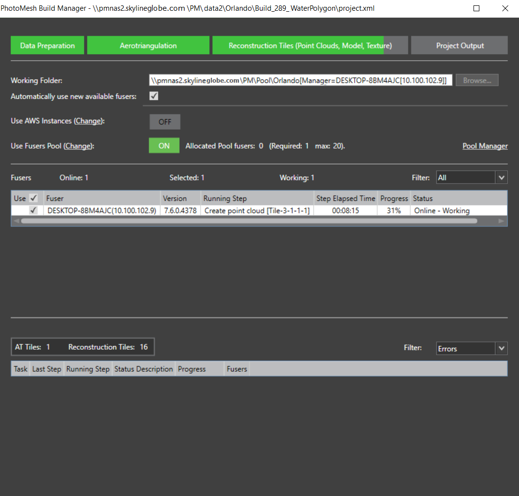
PhotoMesh Build Manager – Starting a Build
6. If you want to change the working folder, in the Working Folder field, click Browse and in the dialog that opens browse to the required folder. See "Setting the Working Folder (on the Master Computer)" in the "Fusers" chapter for information.
7. If you want PhotoMesh to automatically use any new fusers that connect to the project’s working folder, select Automatically use new available fusers. See "Using Fusers" in the "Fusers" chapter for information.
Note: This setting should generally be selected when using AWS and pool fusers.
8. If you want to use AWS fusers, toggle on Use AWS Instances. See "Using Amazon Web Services (AWS) Fusers" in the "Fusers" chapter for information.
9. If you want to use pool fusers, toggle on Use Fusers Pool, and enter the required information. See "Using a Fusers Pool" in this chapter for information
10. Select the required fusers. See "Fuser Management (on the Master computer)" in the "Fusers" chapter and "Monitoring a Build" in this chapter for more information on fusers.
Note: If there are currently no available fusers, a dialog is displayed asking if you want to start a local fuser. Click Yes to start a local fuser. Click No to start the build without adding a fuser; processing will begin automatically when fusers are added. If you want to cancel the build, click Cancel.
11. Click Build.
Setting Advanced Aerotriangulation Parameters
Advanced aerotriangulation settings can be set when building a project or creating a new build version. When rebuilding, aerotriangulation parameters can only be set if the reconstruction step was not started in the previous build. See "Rebuilding" and "Creating a New Build Version" in this chapter for more information.
To set advanced aerotriangulation parameters:
1. Click the Aerotriangulation tab.
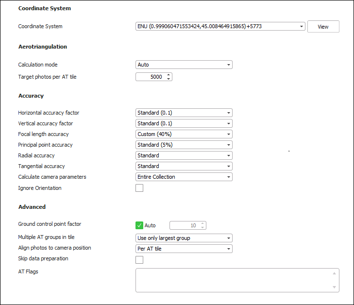
Advanced AT Parameters
2. Set the parameters on the AT tab:
|
Parameter |
Description |
||||||||||
|
Coordinate System |
|||||||||||
|
Project’s internal coordinate system, in which the aerotriangulation and reconstruction are performed. By default, this is set to the coordinate system of the input data. If the inputted data uses multiple coordinate systems, or you want to use a different coordinate system from your input’s, select the required coordinate system. Select the Custom option to create a new custom coordinate system. See "Coordinate System" in the "Basic Concepts" chapter for more information. Note: Click View to view the full Well-Known Text (WKT) for the coordinate system. |
|||||||||||
|
Aerotriangulation |
|||||||||||
|
|
The AT calculation mode that PhotoMesh should use: § Auto – PhotoMesh automatically determines the required calculation mode. If no AT was previously performed, then PM performs a full aerotriangulation ("Calculate AT"). If an AT was previously performed, then it refines the existing AT ("Refine AT"). § Calculate AT – PhotoMesh performs a full aerotriangulation (including matching, bundle adjustment, and GCP) taking into account provided orientation and position information. All previous aerotriangulation calculations performed within PhotoMesh are ignored. § Refine AT –. PhotoMesh reruns the aerotriangulation process (performing only bundle adjustment and GCP). This option is recommended for refining the previously calculated AT or after making changes to the project that can affect the calculated AT, i.e., adding/modifying control points. Refine AT can only be performed if an AT was previously performed or imported from an external source. § Do Not Calculate AT (Fully Trusted) – PhotoMesh uses inputted camera positioning and orientation information and camera parameters (including focal length, principal point and radial/tangential distortion) without performing aerotriangulation. This option is recommended when reliable AT data in a Cartesian coordinate system, such as ENU or ECEF, is added to PM from other AT systems, e.g, Inpho and Bingo. Note: AT data in a projected coordinate system such as UTM may be unreliable either due to earth curvature or earth curvature corrections performed in the other system. This is particularly true for datasets that contain oblique photos or large frames, or cover a large geographic area. For data of this type, aerotriangulation should be re-performed in PhotoMesh, i.e., use the Refine AT option. |
||||||||||
|
Target Photos per AT Tile |
Number of photos to be included in each AT tile. The default setting of 5,000 photos is recommended for most projects and can be efficiently processed on 16 GB computers. For projects requiring more than 5,000 photos per AT tile, the the following RAM guidelines are recommended. Note that the actual RAM needed may be up to twice the suggested amount, varying based on the type of collection, inputted photo information, and specific settings used.
Certain settings or AT-related presets may require more RAM than recommended above. E.g., it is recommended to set the Target Photos per AT Tile to 30% less than the value recommended above in both of the following scenarios: § When using the aggressive match preset § When photo overlap is higher than 75% When running a large AT, it is highly recommended to leave the CPU free of other processes, since the AT process utilizes a large percentage of the available processing power. PhotoMesh includes photos in an AT tile based on the photos' frustum, if orientation information is available, or based on its position and effective range in cases where no orientation information is provided. If the effective range is large and there is a very high overlap of photos, it may be advisable to set the orientation filter to Auto. This filter will try to accelerate the AT process by filtering out photos after a rough calculation of their orientation before proceeding with the remaining aerotriangulation steps. See "Collection Property Sheet" in the "Photo Management" chapter for information about the effective range property. See "Setting Advanced Aerotriangulation Parameters" in the "Building" chapter for more information about the orientation filter. Larger AT tiles with more photos may be necessary if the default AT tiles have fewer than five ground control points that fall in or close to each tile, as is recommended for good accuracy. See the "Control Points" chapter for more information. Note: An AT with a large number of photos may take many hours to complete, and if interrupted will need to be rebuilt. |
||||||||||
|
Accuracy The accuracy of each collection's position and orientation data is set in the collection's property sheet in the Accuracy section. There, you have the option to either input custom values or to select the "Use build settings" alternative to apply the general accuracy settings set in this dialog. If some collections have custom settings, a red notification will display in this dialog informing you of this. |
|||||||||||
|
Horizontal Accuracy Factor |
Weight to assign to the photos’ provided XY coordinates in determining the calculated XY values. This ranges from Very High - External AT (Factor = 10) to Unreliable (Factor = 0). |
||||||||||
|
Vertical Accuracy Factor |
Weight to assign to the photos’ provided altitude in determining the calculated altitude value. This ranges from Very High - External AT (Factor = 10) to Unreliable (Factor = 0). |
||||||||||
|
Focal Length Accuracy |
A percentage that indicates the allowable deviation from the provided focal length value when calculating the AT. This represents the accuracy of the provided focal length. This ranges from Use Input Value to Unreliable. |
||||||||||
|
Principal Point Accuracy |
A percentage that indicates the allowable deviation from the provided principal point when calculating the AT. This represents the accuracy of the provided principal point. This ranges from Use Input Value to Unreliable. |
||||||||||
|
Radial Accuracy |
Camera's radial accuracy. It is generally recommended to select the "Standard" option. If your data was captured with a professional camera that automatically applied a radial distortion correction (i.e., the original distortion value is extremely accurate), select "Use input value". |
||||||||||
|
Tangential Accuracy |
Camera's tangential accuracy. It is generally recommended to select the "Standard" option. If your data was captured with a professional camera that automatically applied a tangential distortion correction (i.e., the original distortion value is extremely accurate), select "Use input value". |
||||||||||
|
Method of calculating the camera’s intrinsic parameters. § Entire collection – Calculate the AT so that the camera intrinsic properties are the same for all photos in the collection. § Per photo – Calculate the camera intrinsics individually for each photo in the collection. Note: Parameters should be calculated per photo when not all of a collection’s photos were taken by the same physical camera with identical focal length and principal point. |
|||||||||||
|
Ignore Orientation |
Select the check box to ignore the provided orientation value. |
||||||||||
|
Advanced |
|||||||||||
|
Ground Control Point Factor |
Weight factor to assign to the ground control points (0-10000) when performing the aerotriangulation. Select Auto to use the default value of 1000. |
||||||||||
|
Multiple AT Groups in Tile |
Select whether to include only a tile’s largest AT group (photo block) or all AT groups in AT Calculated Photos. |
||||||||||
|
Align Photos to Camera Position |
Select one of the following options: § Per AT Tile – Each AT tile is individually aligned to its respective camera positions and ground control points. This option is recommended for projects where most of the AT tiles have enough control points (generally 3 or more) to provide a reliable basis for adjusting the tile's position. Those AT tiles with fewer than three points are adjusted in relation to stable tiles which have an adequate number of control points. This option is recommended for projects with accurate camera positions as well as for nadir and corridor (linear) projects (e.g., roads or rivers) where the AT tile may come out arched. § Entire Project – The entire project is aligned as a single block to the camera positions and ground control points. This option is recommended for projects where very few of the AT tiles have sufficient control points (3 or more) to provide a reliable basis for adjusting the tile's position. |
||||||||||
|
Skip Data Preparation |
When this option is selected, PhotoMesh skips the data preparation step entirely, saving the time that would otherwise be necessary to verify that it had been performed. Only select this option if this step was previously performed, and there has been no change to the AT area or to the project. |
||||||||||
|
AT Flags |
Flags that specify alternate behaviors and settings that PhotoMesh should apply. These flags can be obtained from Skyline support. |
||||||||||
3. Click theReconstruction tab to set advanced reconstruction parameters (see "Setting Advanced Reconstruction Parameters" in this chapter), or click Build to open PhotoMesh Build Manager to start processing (see "Monitoring a Build" in this chapter).
Setting Advanced Reconstruction Parameters
To set advanced reconstruction parameters
1. Click the Reconstruction tab.
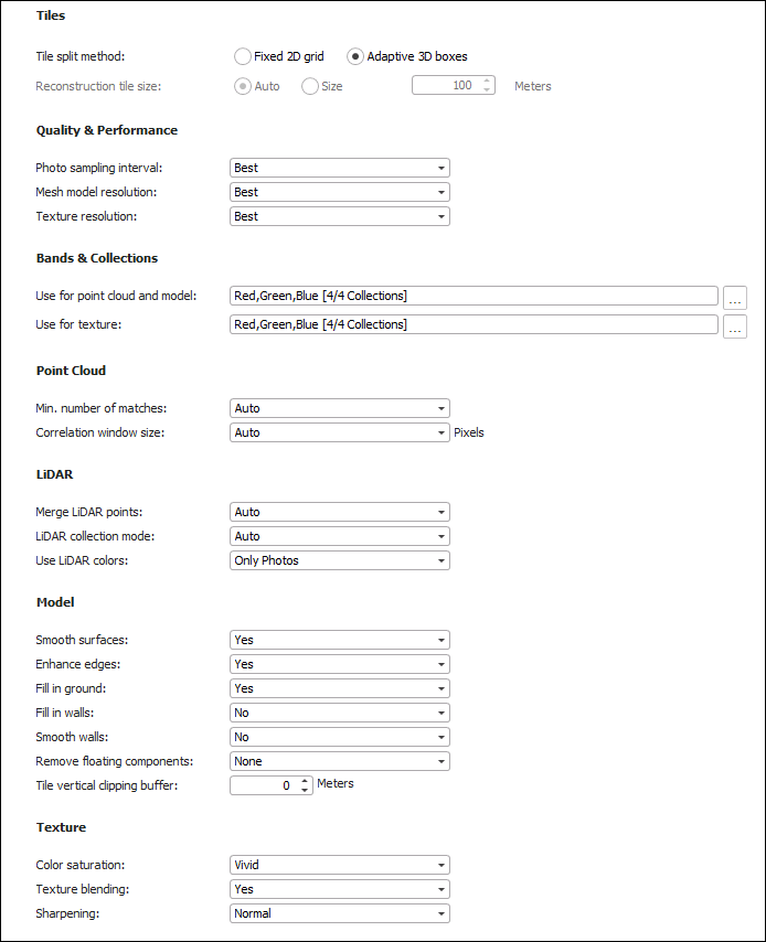
Advanced Reconstruction Parameters
|
Parameter |
Description |
|
Tiles |
|
|
Tile Split Method |
Select either of the following options: § Fixed 2D grid – The reconstruction area is divided into uniformly-sized tiles. § Adaptive 3D boxes – The reconstruction area is divided into 3D tiles in an adaptive manner, based on the memory requirements of each section of the reconstruction area. For example, sections of high resolution or close range, or areas with greater photo coverage, will be split into smaller tiles. The reconstruction area is adaptively divided along the horizontal, vertical and depth axes, allowing for complex three-dimensional data such as tall buildings or utility poles to be split into multiple tiles. When reconstruction tiles are created as adaptive 3D boxes, the display style option is automatically set to"3D Dynamic". In this display mode, the tiles and their boxes are displayed in absolute heights. Tiles that were created one on top of each other will appear as if they are floating in this mode. See "Setting a Reconstruction Tile’s Display Style" in the "Reviewing Your Build" chapter for more information. |
|
Reconstruction Tile Size |
Size of the reconstruction tiles. This can be set to Auto or to a specified size in meters. It is generally recommended to use the Auto option. When tile division results were non-optimal, setting a size in meters is recommended. Note: The size of the reconstruction tiles can only be set when using the 2D grid tile split method. If you want to control tile size based on size in meters, three factors should be taken into account: RAM, resolution and overlap. For projects with standard resolution (5-10 cm photos) 100-150 meters is recommended on computers with 16 GB of RAM. Larger reconstruction tiles require more memory. On computers with over 64 GB of RAM, a tile size up to 400 meters can used be used. As a general rule, the reconstruction tile size should be the ground resolution of the data multiplied by 2000. For high overlap datasets, the ratio between the reconstruction tile size and the ground resolution should be lower. Note: If point cloud build steps are repeatedly failing, and you observe a very high RAM usage towards the end of the point cloud step, it is recommended to reduce memory requirements or reconstruction tile size. |
|
Quality & Performance |
|
|
Photo sampling interval |
The resolution of the photos at which 3D points are extracted for the point cloud: § Best: Extracts points at up to the full resolution of the photo, ensuring the most detailed and high-quality point cloud. This option is recommended in scenarios where the highest quality output is required, even at the cost of extended processing times. § Optimize: Balances quality and efficiency by extracting points at a medium resolution (between 1/4 to 1/2 of the photo's native pixel count). This option reduces processing time to approximately one-third of what is required for "Best" quality output. Note that this setting's impact on quality can vary in comparison to "Best" processing: although medium resolution correlation sometimes leads to slightly reduced quality, in instances where full resolution correlation isn't suited to the image's geometry, it can actually improve output quality. § Low: Offers significantly faster processing compared to the 'Optimize' option by employing low-resolution correlation (at 1/8 of the native pixel resolution), capturing broad geometric details. § Draft: Generates a lower quality point cloud in the fastest processing time. This option provides a broad overview of coverage for preliminary project evaluations. |
|
Mesh model resolution |
Level of mesh complexity. The Low option will aggressively simplify the mesh. |
|
Texture resolution |
The resolution from the photos to use for texturing the model: Best will texture in the exact quality as the photos, while Medium and Low texture with downsampled textures for meshes with smaller textures. |
|
Bands & Collections |
|
|
Use for point cloud and model |
Click the More Options |
|
Use for texture |
Click the More Options |
|
Point Cloud |
|
|
Min. number of matches |
The minimum number of matches required to generate each 3D point. When the point cloud generated is sparse with little overlap of photos, consider reducing the minimum number of matches. When there is noise in the point cloud output, it is recommended to increase the minimum number of matches, providing there is high overlap of the photos. |
|
Correlation window size |
Size in pixels of the window used to perform the correlation between photos and extraction of 3D points from them. |
|
LiDAR |
|
|
Merge LiDAR Points |
The data to use in creating the point cloud: only LiDAR points, only points generated from photos, or Auto – supplement LiDAR with points generated from photos where LiDAR information is insufficient. |
|
LiDAR collection mode |
The direction of LiDAR collection assists in calculating surfaces from the point cloud. When there is no trajectory file and the LiDAR collection is known to be airborne, select Aerial. Otherwise, select Auto. |
|
Use LiDAR colors |
The data to use in texturing the model: § Auto – Supplement photo texture with color from LiDAR points where photo texturing information is insufficient. § Only LiDAR colors – Only color from LiDAR points. § Only photos – Only photo texture. |
|
Model |
|
|
Smooth surfaces |
Determines whether surfaces are flattened. |
|
Enhance edges |
Determines whether 2D edges in the project’s photos are correlated and 3D edges extracted from them, to produce the 3D model. This setting produces better-defined 3D models with sharper edges, which is important for urban area reconstructions and thin structures such as poles and wires. |
|
Fill in ground |
Fills in ground gaps in areas with low coverage by incorporating calculated ground surface. Recommended to improve build results in low overlap, nadir projects. |
|
Fill in walls |
When PhotoMesh detects a vertical gap, it automatically fills in the missing sections to form a complete and continuous vertical surface. This option is only available when "Fill in Ground" is set to Yes. |
|
Smooth walls |
Smooths out vertical surfaces. |
|
Remove floating components |
Level of removal of small floating components in the mesh model (e.g. noise, electric lines, lamp poles). |
|
Tile vertical clipping buffer |
Vertical buffer to apply to the tile. Adding a buffer with a positive value is useful when there are objects that were cut off in a specific tile. A buffer with a negative value can be used to crop areas with small floating components. |
|
Texture |
|
|
Color saturation |
Vividness of the colors of the textured model. |
|
Texture blending |
Determines whether to use data blended from multiple photos in texturing the model, or only data from the optimal photo. Select No if blending results in ghosting artifacts. Select Extra if Yes produces color patches in areas with strong color variance. |
|
Sharpening |
Level of image sharpening applied to the final result. |
|
Advanced |
|
|
Reconstruction flags |
Flags that specify alternate behaviors and settings that PhotoMesh should apply. These flags can be obtained from Skyline support. |
2. Click Next to set output formats (see "Setting Build Steps, Parameters, and Outputs" in this chapter), or click Build to open PhotoMesh Build Manager to start processing (see "Monitoring a Build" in this chapter).
3. To save your building parameters as a Build Preset, click Save as Preset (see "Creating a New Preset" in this chapter) or click Build to begin the build (see "Setting Build Steps, Parameters, and Outputs" in this chapter).
Selecting the Collections and Bands to Include in the Build Outputs
You can select the collections to include when generating the mesh model texture, orthophoto, or point cloud, as well as the bands to include in the orthophoto and to assign to each RGB of the mesh model texture. See "Setting Advanced Reconstruction Parameters" in the "Building" chapter for more information.
To select the collections to include when generating the mesh model texture or point cloud:
1. Click the Reconstruction tab, and then do the following in the Bands and Collections section:
§ In the Use for point cloud and model field, click More Options ![]() - to select collections for the point cloud and model.
- to select collections for the point cloud and model.
§ In the Use for texture field, click More Options ![]() - to select the collections to include in generating the textured model.
- to select the collections to include in generating the textured model.
2. On the Collections tab, select the collections that you want to include for the particular output.
3. Click OK.
To select the bands:
1. Click the Reconstruction tab, and then do the following in the Bands and Collections section:
§ In the Use for point cloud and model field, click More Options ![]() - to select the bands to assign to each of the RGB bands of the mesh model and point cloud, and the collections to include in generating the mesh model and point cloud.
- to select the bands to assign to each of the RGB bands of the mesh model and point cloud, and the collections to include in generating the mesh model and point cloud.
§ In the Use for texture field, click More Options ![]() - to select the bands to assign to each of the RGB bands of the mesh model texture.
- to select the bands to assign to each of the RGB bands of the mesh model texture.
2. On the Bands tab, from the Bands Available section, select a required band, and click Insert ![]() to insert it in the Bands Used section. Insert the bands in the required order. If you want to remove a band from the Bands Used section, select the band, and click Remove
to insert it in the Bands Used section. Insert the bands in the required order. If you want to remove a band from the Bands Used section, select the band, and click Remove ![]() .
.
Note: When selecting bands for mesh texture generation, three bands are required.
3. Click OK.
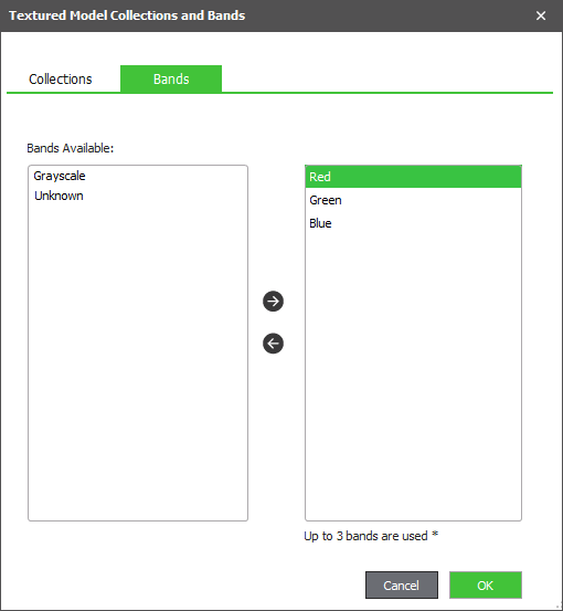
Selecting the Textured Model Collections and Bands
Setting a DAE/OBJ/OSGB Model Pivot
Setting the pivot for a DAE/OBJ/OSGB model improves the stability of its display in 3rd party viewers that are limited regarding display of large coordinates. A DAE/OBJ/OSGB model’s pivot can be set to the project’s center or set to custom coordinates.
To set a DAE/OBJ/OSGB model’s pivot:
1. In the Build Parameters dialog, on the Build Settings (simplified view) tab, in the Outputs section, select Center Pivot to Project.
2. If you want to set a custom pivot, click More Options ![]() . The Pivot Coordinates dialog is displayed.
. The Pivot Coordinates dialog is displayed.
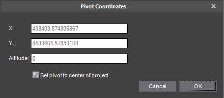
Pivot Coordinates Dialog
3. If you want to set the pivot to the center of the project, select the check box.
4. If you want to set a custom pivot, enter its coordinates.
5. Click OK.