How to Work with the COM Interface
Creating Client Applications
The COM interface is a standard method of communicating between applications. You can develop a client application that utilizes TerraExplorer COM capabilities by using scripting languages (e.g., JavaScript) in an HTML page or by using non-scripting languages (e.g., C++ or C#) in a stand-alone or DLL application. For creating a client application using embedded controls, see How to Work with ActiveX Controls.
Working with Scripting Languages
TerraExplorer interfaces can only be used in a web browser that supports ActiveX controls, primarily Internet Explorer and Microsoft Edge, when used within one of TerraExplorer's built-in containers. There is limited support for display in a standalone web page in the Internet Explorer's legacy IE Mode.
TerraExplorer COM capabilities are incorporated into a web page using the SGWorld object that gives you access to all of its main interfaces. This integration involves two main steps: first, adding the initSGWorld function to your code, and second, instantiating the SGWorld object by calling this function.
Follow these steps to create a Javascript client application using TerraExplorer interfaces:
1. Include initSGWorld Function: Copy the initSGWorld function below into your web page's script to enable the instantiation of the SGWorld object.
<script language="javascript">
function initSGWorld(clsid) {
try {
if (sgworld)
return sgworld.CreateInstance(clsid);
}
catch (e) { }
// Fusion
if (parent && parent.SGWorld) {
return parent.SGWorld.CreateInstance(clsid);
}
// Desktop
try {
// try IE
var obj = document.createElement('object');
obj.setAttribute('id', '__sgworld_ie__');
obj.setAttribute('classid', 'CLSID:3a4f91a0-65a8-11d5-85c1-0001023952c1');
document.body.appendChild(obj);
return __sgworld_ie__.CreateInstance(clsid);
} catch (e) { } //Not IE
try {
// Try Edge
return __sgworld__.CreateInstance(clsid)
} catch (e) { } // Not Edge
return null;
}
</script>
2. Instantiate SGWorld: Once initSGWorld is included, call the function to create an instance of SGWorld.
var SGWorld = initSGWorld("");
Note: It is recommended to pass an empty string "" to get the latest version of SGWorld. For a specific version of SGWorld, consult that version's user guide for the correct clsid. TerraExplorer Fusion will always return the latest version regardless of the clsid passed.
3. Access the main interfaces – The SGWorld object exposes an ISGWorld interface based on the parameter passed to initSGWorld. Using this interface you can access all the main TerraExplorer interfaces. For example, to zoom in you will need to call the INavigate80.ZoomIn method:
SGWorld.Navigate.ZoomIn();
See “Creating an HTML Client Application” in the “Examples in JavaScript” chapter for an example of how to initialize SGWorld and create a basic HTML to which to add the TerraExplorer COM interfaces using JavaScript.
Working with C#
Using C# or any non-scripting language allows you to develop more complex and powerful client applications.
The instructions provided here refer to Microsoft Visual Studio 2017.
Follow these steps to create a C# client application using TerraExplorer Interfaces:
1. Set Project References – From the Project menu, select Add Reference. Select the COM tab, locate TerraExplorerX 1.0 Type Library from the available references, select its check box, and then click OK.
Note: When a reference to a COM component is added to a .NET project an interop DLL is automatically created. You can find “Interop.TerraExplorerX.dll” in the obj folder of your project. This DLL intermediates between the COM and .NET components.
2. Add Using directive – To access types in the TerraExplorerX namespace.
using TerraExplorerX;
3. Define Variable for SGWorld Object – Declare an SGWorld variable.
private SGWorld80 sgworld;
4. Create TerraExplorer Object – Use new to reference the variable to the SGWorld object.
this.sgworld = new SGWorld80();
5. Access the main interfaces – Using this object you can access all the main TerraExplorer interfaces. For example to zoom in you will need to call the INavigate80 ZoomIn method:
sgworld.Navigate.ZoomIn();
Asynchronous Requests
TerraExplorer API provides an asynchronous implementation for methods that involve time-consuming operations, such as executions in separate threads or initiation of HTTP requests. While these methods also have a legacy synchronous implementation, it is generally recommended to use the asynchronous one for optimal performance. Synchronous requests block the execution of the calling code, resulting in a "freezing" effect on the 3D Window and an unresponsive user experience. Asynchronous requests avoid this problem by providing a callback when the threaded execution is complete, allowing the browser or calling application to continue functioning normally while your request is being handled. Note that only asynchronous calls are supported for browser calls to TerraExplorer Fusion.
Each asynchronous method in the TerraExplorer API immediately returns either the ITerraExplorerAsync80 or the ICommandLineProcessAsync object, thereby ensuring that control is promptly handed back to the calling function. These objects provide a callback-based mechanism similar to the JavaScript promise and the C# Task that allows handling the various stages of the asynchronous operation.
The ITerraExplorerAsync80 object provides the following properties and methods:
§ OnResolve: This method includes a callback function that is called when the asynchronous operation is successfully resolved. If a corresponding synchronous method has a return value, it's passed as a parameter to the callback function.
§ OnReject: This method includes a callback function that is called when the asynchronous operation encounters an error or is rejected, allowing you to handle any failures or exceptions. It returns an error message.
§ OnProgress: This method includes a callback function that is called to report the progress of the asynchronous operation, providing updates on the ongoing task. This function is only implemented for ExecuteQueryAsync and QueryElevationBufferAsync.
§ State: This property returns the current state of the asynchronous operation (pending, fulfilled, rejected), allowing you to check its status.
§ Abort: This method can be used to abort or cancel the ongoing asynchronous operation if needed.
Example of asynchronous method that returns the ITerraExplorerAsync80 object
function CreateShapeAsync()
{
var g_asyncObj = SGWorld80.Creator.CreateFeatureLayerAsync("ShapefileAsync", "FileName=C:\\Shapes\\countries.shp;TEPlugName=OGR;");
g_asyncObj.OnResolve(function(layer){
layer.FeatureGroups.Point.DisplayAs = 18;
layer.LoadAsync();
});
}
See "Wrapping TE Async Object with a JavaScript Promise" for an example of wrapping TE Async Object with a JavaScript promise.
The ICommandLineProcessAsync object provides the following methods:
§ OnStdout: This method is called when the command line process sends information to the standard output (stdout).
§ OnStderr: This method is called when launched command line process encounters an error.
§ OnExit: This method is called when the command line application exits.
§ Abort: This method can be used to abort or cancel the command line process.
Example of asynchronous method that returns the ICommandLineProcessAsync object
g_asyncObj = SGWorld.Creator.CreateCommandLineProcessAsync("my.exe param1 param2").OnStdout(function(stdout){
g_stdout += stdout;
g_asyncObj.Abort();
}).Onstderr(function(stderr){
g_stderr+=stderr;
}).OnExit(function(exitCode){
alert(exitCode);
alert(g_stderr);
alert(g_stdout);
});
HRESULT Return Values
All COM methods return an unsigned integer called an HRESULT that tells whether the method succeeded or failed and provides additional information about the outcome of the operation.
The return value obtained from the returned HRESULT of TerraExplorer calls can be one of the following:
|
Return value |
Meaning |
|
S_OK |
Success. |
|
E_FAIL |
Catastrophic failure. |
|
TE_E_INTERNAL |
TerraExplorer was unable to create the object. To get more information about this error use IErrorInfo Interface. |
|
TE_E_NOLICENCE |
Your license does not allow the use of this feature. |
|
TE_E_MPTNOTLOADED |
A terrain database file must be loaded in TerraExplorer for this method to work. |
|
For operations involving objects, the following HRESULTS are also returned: |
|
|
TE_E_TEOBJECT_NOLONGEREXIST |
The object you are trying to access no longer exists. This may have occurred because, while keeping an interface to the object/feature, the user deleted it from TerraExplorer (via the TerraExplorer user interface) or the feature was removed by the streaming mechanism. Without the object, the interface cannot be used. Therefore, you should release the interface. |
|
TE_E_OBJMANAGER_OBJNOTFOUND |
The requested object was not found. |
Controlling the Camera
The example code in this section is written in JavaScript. In order to embed this code in an HTML page, the initSGWorld function must be added to your code, and then the SGWorld object must be instantiated by calling this function. See "Working with Scripting Languages" in this chapter for more information.
TerraExplorer allows the client application to set and retrieve the camera position via its INavigate80 interface. There are several typical scenarios in which this interface is needed:
Getting the current position of the camera
In this scenario the client needs to know where the TerraExplorer user is currently located in the 3D World in order to perform a task. An example for this might be a client HTML page with a button that, when pressed, gives the user directions to the closest movie theater or other points of interest. In this scenario, the client should use the INavigate80 interface to call the GetPosition method:
var pos = SGWorld.Navigate.GetPosition();
Jumping to a new location
In this scenario, the client application prompts the camera to jump to a new position in the 3D World. In this example the client application should create the position using the ICreator80 interface and then call the INavigate80.SetPosition method:
var pos = SGWorld.Creator.CreatePosition(-71.05216, // X
42.34569, // Y
1000, // Altitude
0, //AltitudeTypeCode.ATC_TERRAIN_RELATIVE, // Altitude type
0.0, // Yaw
-43.0); // Pitch
SGWorld.Navigate.SetPosition(pos);
Flying to a new location
A destination location can be a specific position in the 3D World or the current coordinates of locations or objects in the project. To fly to a specific position, the client application should create the position using the ICreator80 interface and call the FlyTo method. To fly to the current position of a location or object, the client application should pass the object to the FlyTo method:
var circle = SGWorld.Creator.CreateCircle(SGWorld.Creator.CreatePosition(-71.00864, 42.36229,0,2),
1000.0, SGWorld.Creator.CreateColor(0, 0, 0, 0), SGWorld.Creator.CreateColor(200, 50, 50, 128) );
circle.Position.Distance = 3000;// The camera will look at the object from a distance of 3000 meters
SGWorld.Navigate.FlyTo(circle);
Dynamically controlling the position of the camera in each frame
This is the most advanced technique for controlling the camera. In this scenario, the client application might need to move the camera position in each frame as a dependency in other inputs. There are two steps the client application needs to follow:
1. Using the_ISGWorld80Events.OnFrame event handler – TerraExplorer sends this event before it is about to render a new frame. The client application can use this opportunity to move the plane to a new position.
2. In the event handler routine, call Inavigate80.SetPosition.
Note: This solution does not work well with scripted languages because of a severe performance penalty.
SGWorld.AttachEvent("onFrame", onFrame);
function onFrame()
{
var pos = SGWorld.Navigate.GetPosition();
pos.X += 0.5;
pos.Y -= 0.2;
SGWorld.Navigate.SetPosition(pos);
}
Project Tree Management
The IProjectTree80 interface gives the client access to all of the objects and elements in a project through the Project Tree structure. Client applications can control the appearance of the Tree (i.e. expand groups, move items from one group to another etc.), delete single entries or entire groups from the Tree and add their own content to it.
The example code in this section is written in JavaScript. In order to embed this code in an HTML page, the initSGWorld function must be added to your code, and then the SGWorld object must be instantiated by calling this function. See "Working with Scripting Languages" in this chapter for more information.
Creating and modifying groups
Using the IProjectTree80 interface you can create new groups in the project. You can create regular groups or locked groups under the root area or any other group in the Tree. Using the IProjectTree80 interface you can also modify existing groups (i.e. expand or collapse a group using the IProjectTree80.ExpandGroup method)
Finding and modifying objects in a project
One of the most important capabilities of the IProjectTree80 interface is to provide a means of traversing the TerraExplorer Project Tree. This, in conjunction with other features, is a very powerful tool that can be used to achieve many different goals. For example, the client can traverse the Tree to change the color for all objects or a subset of them, or to present the project’s content in another format. Traversing the Tree might also be used to search for items in the project that match a set of criteria (i.e. all the models that are in a certain area on the terrain). You can even delete objects from the project using the IProjectTree80.DeleteItem method.
var node = SGWorld.ProjectTree.GetNextItem(group, 11); // code 11 get the first child in the group
while (node > 0)
{
var object = SGWorld.ProjectTree.GetObject(node);
// Here you can perform operations on the object.
node = SGWorld.ProjectTree.GetNextItem(node, 13); // code 13 gets the next sibling
}
Object Management
Client applications can add, modify and remove TerraExplorer objects. This enables a whole new level of customization and richness in features such as importing/exporting new files formats, controlling the movements of objects on the terrain from local and remote devices, and more.
The example code in this section is written in JavaScript. In order to embed this code in an HTML page, the initSGWorld function must be added to your code, and then the SGWorld object must be instantiated by calling this function. See "Working with Scripting Languages" in this chapter for more information.
Adding objects to the project
ICreator80 is the interface that provides the methods to create all the different types of layers, objects, locations and presentations in the project. Using one of the Create methods (i.e. ICreator80.CreateCircle) you can add the objects to the project and place them in any location in the 3D World. When the client application creates such an object, it gets an interface to the object in return, which can then be used to perform further operations on it.
var circle = SGWorld.Creator.CreateCircle(SGWorld.Creator.CreatePosition(-71.00864, 42.36229,0,2), // Pivot
1000.0, // Radius (1000m)
SGWorld.Creator.CreateColor(0, 0, 0, 0), // Outline color (in this sample, transparent/no outline)
SGWorld.Creator.CreateColor(200, 50, 50, 128) // Fill color
);
Modifying objects’ parameters
Using the ICreator80 and the IProjectTree80 interfaces, you can get an interface to TerraExplorer objects. If the client application created this object, you should have the interface as a return value from the CreateXX method. You can also get an interface from an item ID by using the IProjectTree80.GetObject method.
var node = SGWorld.ProjectTree.GetNextItem(group, 11); // code 11 get the first child in the group
while (node > 0)
{
var object = SGWorld.ProjectTree.GetObject(node);
// Here you can perform operations on the object.
node = SGWorld.ProjectTree.GetNextItem(node, 13); // code 13 gets the next sibling
}
TerraExplorer Events
TerraExplorer provides an extensive set of events for clients, allowing them to know when the user performs operations on objects (i.e. edits them or flies to them) or intercepts messages before they are sent to their destination containers (allowing the client to modify them or to display them himself). Controlling the camera or objects on the terrain continuously (in a smooth movement) is also made possible with the help of the OnFrame event. A client can update the position of the objects/camera in each frame by handling this event.
Events should be handled according to the way your environment handles COM events. See “Opening a Project in C#” for an example of usage of the += operator in C# and “Opening a Project in JavaScript” for an example of the AttachEvent in JavaScript.
Note: When working in C# out of process, events may be received on a thread other than the subscribing one. When executing UI work in event callback, make sure to transfer control to the UI thread.
|
|
Events |
|
|
|
This event occurs when a distance analysis point is added. |
|
|
|
Notifies the client of the analysis progress. |
|
|
|
|
This event occurs when a TerraExplorer ribbon command is executed, and can be used to discover the ICommand.Execute API for each ribbon command. |
|
|
This event occurs when a standard TerraExplorer ribbon command’s value is changed. |
|
|
|
This event occurs when an operation is performed on a project’s custom containers. |
|
|
|
OnCreateBasicKit |
Reserved. No longer used |
|
|
This event is triggered when the ID of the feature that was assigned by the data source is changed. |
|
|
|
This event occurs when the date and time settings are changed to a specific date and time. |
|
|
|
This event is sent in each frame, after the frame is rendered, but before the HUD layer is drawn. |
|
|
|
This event occurs when a drawing action is aborted. |
|
|
|
This event occurs when a drawing action is finished. |
|
|
|
This event occurs when a drawing object’s geometry is changed. |
|
|
|
This event occurs when a measurement is finished (all measurement points were added). |
|
|
|
This event occurs when a feature layer was changed. |
|
|
|
This event occurs when a feature layer was saved. |
|
|
|
This event occurs when a Fly file is closed. |
|
|
|
This event occurs when a file is being closed. |
|
|
|
This event occurs when a Fly file is being saved. |
|
|
|
This event occurs, before the frame is rendered, to allow the client to perform any per frame activities (i.e. moving objects on the terrain). |
|
|
|
This event indicates to the client the current status of the import process. |
|
|
|
This event occurs when the TerraExplorer Input mode is changed (e.g., switching from free flight mode to measurements mode). |
|
|
|
This event occurs when a key on the keyboard is pressed or released. |
|
|
|
This event occurs when a layer is streamed from the server without first storing it in a client local file. |
|
|
|
This event occurs when the user clicks the left mouse button. |
|
|
|
This event occurs when the user double-clicks the left mouse button. |
|
|
|
This event occurs when the user presses the left mouse button. |
|
|
|
This event occurs when the user releases the left mouse button. |
|
|
|
This event occurs when TerraExplorer finishes loading a Fly file. |
|
|
|
This event occurs when the user presses the middle mouse button. |
|
|
|
This event occurs when the user presses the middle mouse button. |
|
|
|
This event occurs when the user releases the middle mouse button. |
|
|
|
This event occurs when the results are returned for an area measurement. |
|
|
|
This event occurs when the results are returned for a distance measurement. |
|
|
|
This event occurs when the results are returned for an information query. |
|
|
|
This event occurs as a user rotates the mouse wheel and encounters the wheel’s next notch. |
|
|
|
This event occurs when loading of a KML network link fails. |
|
|
|
This event occurs when certain actions (e.g., fly to an object) are performed on the object. |
|
|
|
This event occurs when an object is selected in the 3D Window. |
|
|
|
This event occurs when the object under the cursor is changed. |
|
|
|
This event occurs when an object is unselected in the 3D Window. |
|
|
|
This event occurs when any change occurs in the running of a presentation, e.g., presentation started, action started, or action finished. |
|
|
|
This event occurs when a presentation’s play status changes status. |
|
|
|
This event occurs when certain actions (e.g., showing and hiding items) are performed on Project Tree items. |
|
|
|
|
This event occurs when the publishing of a project is aborted. |
|
|
|
This event occurs when the publishing of a project is finished. |
|
|
|
This event provides the client information regarding the publishing process. |
|
|
This event occurs when the user double-clicks the right mouse button. |
|
|
|
This event occurs when the user presses the right mouse button. |
|
|
|
This event occurs when the user releases the right mouse button. |
|
|
|
This event occurs whenever the terrain quality that the user is currently viewing is updated. |
|
|
|
This event occurs when a specifiedTerraExplorer event takes place. |
|
|
|
This event occurs when a message object is about to be triggered. |
Coordinate Systems
With TerraExplorer, the client application can use a different coordinate system from that of the terrain database. The ICoordServices80 interface provides a set of methods for reprojecting given coordinates between different coordinate systems. Use the SourceCoordinateSystem property to define the coordinate system your application uses. Once a coordinate system has been set by a client, every coordinate used by the client is converted from the source coordinate system used by the client to the terrain coordinate system. Also, any coordinate returned from TerraExplorer (e.g., INavigate80.GetPosition) is converted from the coordinate system of the terrain, to the client coordinate system.
TerraExplorer also provides a number of service methods to perform advanced geographic-related tasks like converting units to metric value, calculating distances and angles between points. These methods are especially useful when working with globe databases, where the units are in degrees, but work for any database.
Well-Known Text and Well-Known Binary (WKT and WKB)
Well-known text (WKT) is a text markup language for representing vector geometry objects on a map and spatial reference systems of spatial objects. A binary equivalent, known as well-known binary (WKB) is used to transfer and store the same information for geometry objects. Both formats are regulated by the Open Geospatial Consortium (OGC). The background information brought here draws on OGC and Wikipedia articles on the topic. See: http://www.opengeospatial.org/standards/sfa and http://en.wikipedia.org/wiki/Well-known_binary.
Well-Known Text representation of spatial reference systems
The Well-Known Text representation of spatial reference systems provides a standard textual representation for spatial reference system information. A spatial reference system, also referred to as a coordinate system, is a projected (X, Y), geographic (latitude-longitude), or geocentric (X, Y, Z) coordinate system. A data set's coordinate system is identified by the PROJCS keyword if the data are in projected coordinates, by GEOGCS if in geographic coordinates, or by GEOCCS if in geocentric coordinates (A geocentric coordinate system has its origin at the center of the Earth).
§ For projected coordinates, the PROJCS keyword is followed by all of the components which define the projected coordinate system: the projected coordinate system name, the geographic coordinate system, the map projection, 0 or more parameters, and the linear unit of measure.
§ A geographic coordinate system is defined by its name, the datum, the prime meridian, and the angular unit of measure.
§ A geocentric coordinate system, quite similar to a geographic coordinate system, is defined by its name, the datum, the prime meridian, and the linear unit of measure.
Each system component has a keyword in upper case (for example, DATUM or UNIT) followed by the defining, comma-delimited, parameters of the component in brackets. Some components are composed of sub-components so the result is a nested structure.
Example Coordinate System WKT
PROJCS["Zone 10N (126 W to 120 W)",
GEOGCS["WGS84 Coordinate System",
DATUM["WGS 1984",
SPHEROID["WGS 1984",6378137,298.257223563],
TOWGS84[0,0,0,0,0,0,0],
AUTHORITY["EPSG","6326"]],
PRIMEM["Greenwich",0],
UNIT["degree",0.0174532925199433],
AUTHORITY["EPSG","4326"]],
PROJECTION["Transverse_Mercator"],
PARAMETER["false_easting",500000],
PARAMETER["false_northing",0],
PARAMETER["latitude_of_origin",0],
PARAMETER["central_meridian",-123],
PARAMETER["scale_factor",0.9996],
UNIT["METERS",1],
AUTHORITY["EPSG","32610"],
AUTHORITY["SBMG","UTM,UTM-10N,WGS84,METERS"]]
Well-Known Text representation for geometric objects
The Well-Known Text representation for geometric objects can be used both to construct new instances of the type and to convert existing instances to textual form for alphanumeric display. Geometric objects that can be represented with WKT include: points, lines, polygons, multi-geometries that represent more than one geometry of the same dimension in a single object, and geometry collections that store geometries of different dimensions.
The Well-Known Text description is made up of three components: geometry type, coordinate type, and coordinate list. The coordinate type specifies whether or not the geometry has Z coordinates and/or a linear referencing system. If the geometry has neither, this argument is left blank. If the geometry has Z coordinates, the coordinate type is set to Z, if the geometry has a linear referencing system, it is set it to M and if it has both, then to ZM.
The coordinate list defines the double-precision vertices of the geometry. Coordinate lists are separated by commas and enclosed by parentheses. If a geometry has multiple components, parentheses must enclose each component part (e.g. MultiPoint ((10 10), (20 20))) If the geometry is empty, the keyword EMPTY follows the geometry type.
The following are some example geometric WKT strings.
|
Geometry Type |
Text Literal Representation |
Comment |
|
Point |
Point (4 6) |
A Point |
|
Point |
Point ZM (1 2 5 40) |
A Point with Z coordinates and a linear referencing system. |
|
Point |
Point M (1 2 80) |
A Point with a linear referencing system. |
|
Point |
Point Empty |
An empty geometry |
|
LineString |
LineString ( 10 10, 20 20, 30 40) |
A LineString with 3 points |
|
Polygon |
Polygon ((10 10, 10 20, 20 20, 20 15, 10 10)) |
A Polygon with 1 exteriorRing and 0 interiorRings |
|
Multipoint |
MultiPoint ((10 10), (20 20)) |
A MultiPoint with 2 points |
|
MultiLineString |
MultiLineString ( (10 10, 20 20), (15 15, 30 15) ) |
A MultiLineString with 2 linestrings |
|
MultiPolygon |
MultiPolygon ( ((10 10, 10 20, 20 20, 20 15, 10 10)), ((60 60, 70 70, 80 60, 60 60 )) ) |
A MultiPolygon with 2 polygons |
|
GeomCollection |
GeometryCollection ( POINT (10 10), POINT (30 30), LINESTRING (15 15, 20 20) ) |
A Geometry Collection consisting of 2 Point values and a LineString value |
Well-Known Binary representation for geometry
The Well-Known Binary Representation for Geometry (WKBGeometry) provides a portable representation of a geometric object as a contiguous stream of bytes:
§ The first byte in the stream identifies how the binary values are represented, either: NDR (Network Data Representation or XDR (eXtended Data Representation). The difference between the two encodings is byte order. NDR is little endian, which means that an unsigned integer – a 32-bit data type that encodes a nonnegative integer - stores the least significant byte first, while a double – a 64-bit double precision data type that encodes a double precision number using the IEEE 54 double precision format - stores the sign bit as the last byte. XDR is big endian, so the byte order is reversed.
§ The next component in the stream indicates the geometry type. Values from 1 through 7 indicate Point, LineString, Polygon, MultiPoint, MultiLineString, MultiPolygon, and GeometryCollection.
§ If a geometry consists of multiple geometries, additional bytes indicate the number of geometries.
§ The next byte component indicates the number of points in the first shape, followed by the X,Y coordinates of each of the points. For each additional shape, a byte indicates the number of points, followed by bytes defining each point’s coordinate values.
Client Data
Each TerraExplorer object and Project Tree group has a text string assigned to it; this information is called the client data, and it is saved in the TerraExplorer Fly file. The client data is used for saving attribute information about a specific group or object and for saving information relating to your application.
To avoid conflicts between TerraExplorer and different client applications, the client data is arranged in Namespaces. Each Namespace is defined by a string identifier. You should define the Namespace identifier from which to store or retrieve data. For example, you can use “MyApplication” as an identifier for your information.
For Groups, you can access the client data using the IProjectTree80.SetClientData and IProjectTree80.GetClientData methods. You can write your own custom string, or update the current one.
For Objects, any object derived from IterraExplorerObject80, has SetClientData and GetClientData methods.
Feature Layer Connection Strings
A feature layer is a complex TerraExplorer object designed to display feature datasets from different sources.
A connection string standard is used to define connections to various layer source file formats and servers. The connection string specifies information about the data source and the means of connecting to it. The string is then passed to ICreator.CreateFeatureLayer to create the new layer.
See “Feature Layers” chapter in the TerraExplorer User Manual for additional information.
The connection string contains a series of parameters separated by semicolons (;). The string consists of a series of keyword/value pairs separated by semicolons. The equal sign (=) connects each keyword and its value.
For example, this connection string loads the shapefile “C:\sample.shp” as a layer:
“FileName=C:sample.shp;TEPlugName=OGR;“
The following parameters are supported:
§ TEPlugName=OGR – Used to load layers from the following data sources. An additional parameter is required as described below:
· Shapefile:
“FileName=FullPathToShapeFile”
Where FullPathToShapeFile defines a full path to the shapefile.
· DGN file:
“FileName=FullPathToDGNFile”
Where FullPathToDGNFile defines a full path to the DGN file.
· DXF file:
“FileName=FullPathToShapeFile”
Where FullPathToShapeFile defines a full path to the DXF file.
· Oracle Spatial:
“OGRConnectionString= OCI:userid/password@database_instance:table,table”.
Where userid/password defines respectively the user name and password required for connecting to the server, database_instance defines the Oracle Net Service name, and table defines the table to access.
· PostgreSQL extended with the PostGIS spatial data support:
LayerName=LayerName;OGRConnectionString={ PG:dbname=’databasename’}”
Where databasename defines the database name.
Additional parameters may be provided as required, e.g. { PG:dbname=’databasename’ host='addr' port='5432' user='userid' password='password'}.
· MongoDB:
"LayerName=LayerName;OGRConnectionString=mongodb+srv://UserName:Password@Host/DatabaseName"
Where UserName:Password define respectively the user name and password for connecting to the service, Host defines the IP address of the database, and DatabaseName defines the database name.
· MS SQL Spatial:
“OGRConnectionString={ MSSQL:server=servername;database=databasename;UID=userid;PWD=password;Tables=table}”
Where servername defines the server name, databasename defines the database to connect to, userid and password define the user name and password respectively, and table defines the table to access.
· Esri:
"FileName=ServerURL;LayerName=ESRIJSON;SeverURLExtraParams=Token"
Where FileName defines a full URL to the layer, e.g. https://services.thelist.tas.gov.au/arcgis/rest/services/Public/CadastreAndAdministrative/MapServer/4 and LayerName is always set equal to ESRIJSON and ServerURLExtraParams sets additional parameters to send to the server e.g. token.
· SQLite:
“FileName=FullPathToSQLiteFile;LayerName=LayerName”
Where FullPathToSQLiteFile defines a full path to the SQLite file, LayerName defines the name of the layer to be loaded.
· GeoDatabase:
“FileName=FullPathToGeoDatabaseFile;LayerName=LayerName”
Where FullPathToGeoDatabaseFile defines a full path to the GeoDatabase file, LayerName defines the name of the layer to be loaded.
· GeoPackage:
“FileName=FullPathToGeoPackageFile;LayerName=LayerName”
Where FullPathToGeoPackageFile defines a full path to the GeoPackage file, LayerName defines the name of the layer to be loaded.
· GeospatialPDF:
“FileName=FullPathToGeospatialPDFFile;LayerName=LayerName”
Where FullPathToGeospatialPDF defines a full path to the Geospatial PDF file, LayerName defines the name of the layer to be loaded.
§ TEPlugName= WFS – Used to load layers from Web Feature Server (WFS). Additional parameters are required (mandatory fields are bolded):
· Server:
“Server=ServerURL”
Where ServerURL defines a full URL to the server.
· WFSVersion:
“WFSVersion =Version”
Supported Version values are “1.0.0” and “1.1.0”.
· LayerName:
“LayerName=LayerName”
Where LayerName defines the name of the layer to be loaded.
· User:
“User=UserName”
Where UserName defines the user name required to connect to the server.
· Password:
“Password=Password”
Where Password defines the user name required to connect to the server.
· Lat-Long or Long-Lat coordinate format:
“CRS_XY_OR_YX=Format”
Supported Format values are “1” for Long-Lat and “2” for Lat-Long.
§ TEPlugName=GeoDatabase – Used to load layers from a Personal Geodatabase file. Additional parameters are required (mandatory fields are bolded):
· LayerName:
“LayerName=ServerURL”
Where LayerName defines a full path to the GeoDatabase file.
· TableName:
“TableName =TableName”
Where LayerName defines the name of the table containing the layer to be loaded.
§ TEPlugName= DSN – Used to load layers from an ODBC database connection. Additional parameters are required (mandatory fields are bolded):
· DSNPlugName:
“DSNPlugName=PlugName”
Where PlugName defines the ODBC driver. For example: “Microsoft Access(*.mdb)”.
· DSNConnectionString:
“DSNConnectionString=ConnectionString”
Where ConnectionString defines the DSN connection string as required by the defined driver.
· DSN_X_Field:
“DSN_X_Field=X”
Where X defines the database field name containing the X coordinate.
· DSN_Y_Field:
“DSN_Y_Field=Y”
Where Y defines the database field name containing the Y coordinate.
· DSN_AltitudeField:
“DSN_AltitudeField=Altitude”
Where Altitude defines the database field name containing the altitude value.
· TableName:
“TableName=TableName”
Where LayerName defines the name of the table containing the layer to be loaded.
An existing layer can be manipulated and controlled using the IFeatureLayer80 interface. This includes controlling appearance of the feature and annotation information, managing the streaming behavior, and adding and removing individual items.
Standard Units, Time Formats and Angular Representations
Units
Although a TerraExplorer user can control the display and editing units of several types of parameters, the COM interface always uses the same types of units.
Unit definitions:
§ X, Y Coordinates – The X and Y coordinates should be presented in the same coordinate system that the project’s terrain database uses. For Lat-Long terrains, a decimal Lat-Long presentation should be used.
§ Altitude and Height – Altitude and height values should be presented in meters above ground. For 2D primitives you can use meters above the object’s pivot point.
§ Distance – Distances and dimensions of objects should be presented in meters.
§ Speed – Speed should be presented in meters per second.
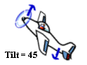
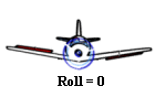
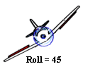
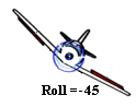
Yaw, Pitch and Roll Angles
The yaw (direction), pitch (tilt) and roll values are defined as described in the following diagram.
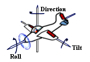
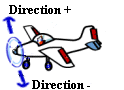
Yaw values
Range from 0 to 360 where 0=North, 90=East, 180=South and 270=West. TerraExplorer Pro adjusts illegal values to this range by modulating the illegal number.
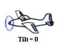
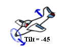
Pitch values
Range from -90 to +90 where 0 = horizon, +90 = straight up and –90 = straight down. TerraExplorer Pro adjusts illegal values to this range by modulating the illegal number.
Roll values
Range from -90 to +90 where 0 = horizon, +90 = full roll right and –90 = full roll left. TerraExplorer Pro adjusts illegal values to this range by modulating the illegal number.
Time values can be expressed as any of the following:
§ JavaScript Date object
§ VT_DATE
Note: DateTime (e.g. in JavaScript) is automatically converted to VT_DATE.
· _time_t
Int or long values representing the number of seconds elapsed since 00:00:00 on January 1, 1971, Coordinated Universal Time.
· double
Double values representing the number of milliseconds elapsed since 00:00:00 on January 1, 1971, Coordinated Universal Time.
§ C# DateTime object.