Creating a New Building
The Building feature allows you to add 3D models to the project by manually defining the geometry of the building rooftop and stretching it above the basic terrain, or by loading the rooftop geometry from external feature layers.
You can define the shape of the roof as a flat surface, or as an angular surface. After defining the building geometry, you can assign fill color and texture from external files or apply texture from the terrain to the roof and side walls.
To create a new building:
1. On the Objects tab, in the 3D Objects group, click Building.
2. With the cursor in the 3D Window, click the mouse to add the first point of the roof.
3. Click again to add additional points of the roof’s polygon until you have marked the entire shape. You must place at least three points to define the roof.
Note: When creating a building, the lines of the roof polygon should not overlap each other. This may result in an irregular object.
Note: It is recommended to keep the number of roof points to the minimum required to define the shape. Adding unnecessary points may adversely affect performance.
4. Right-click to finish the roof polygon.
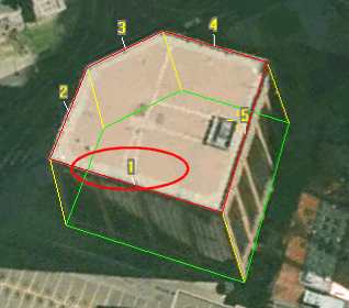
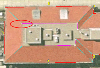
5. If there is a horizontal offset between the roof and the building base in the aerial/satellite imagery, use the mouse pointer to drag the base polygon (in green) to its place on the imagery and left click to finish the operation.
6. If there is no horizontal offset between the roof and the building base in the aerial/satellite imagery right-click again to finish the operation.
7. Enter the roof height of the building under Geometry in the Building property sheet.
8. Continue to edit the building’s parameters and shape, or close the property sheet to finish the operation.
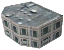
Example of a Building Object
Defining Roof and Wall Fill Types
For each of a building’s sidewalls and its roof, you can assign a fill that is a single color, a texture from a file, or a texture from the terrain pattern. A different fill type can be assigned to each face of the building.
To change a building’s fill type:
1. In the Texture section of the property sheet, in the Selected Face field, select the required surface.
2. In the Face Fill Type field, select the required fill type.
Note: You can select the Terrain Texture option for sidewalls only if the building has an offset between the roof and the base frames.
3. For each surface for which you select Terrain Texture as the fill type, assign the Face Terrain Texture parameter. If a wall has an exposed texture on the satellite/aerial imagery, you should use its own texture. If the wall’s texture in not available, you can assign the texture from one of the other exposed walls.
Note: It is recommended not to break an exposed wall into sub-walls. This allows you to use the entire wall texture for non-exposed walls.
4. For each surface for which you select Single Color as the fill type, select a Face Color.
5. For each surface for which you select Image File Texture as the fill type, browse to the required Face Texture File.
Modifying the Building Geometry and Position
After creating the building’s initial geometry, you can still modify it by selecting one of the top bar tools and editing the building shape in the 3D Window.
|
Mode |
Description |
|
2D View mode |
While editing the building’s base, roof and angular roof geometry, the building is displayed in 2D View mode. In this mode, you can view and edit the buildings outlines and nodes. |
|
3D Window mode |
This option displays the building as a complete 3D model. Use this option to edit the height of the building and view the result of your 2D editing. |
Building Properties Window Top Bar
|
Icon |
Function |
Activity |
|
|
Edit roof/base position |
Select this option to move the building’s roof, base or the entire shape. § Click and drag the green polygon to move the base frame. § Click and drag the red polygon to move the roof frame. § Click and drag the yellow line to move the entire building. |
|
|
Edit roof/base nodes |
Select this option to move, add or delete nodes on the base or roof frames. § Click and drag a node on the green polyline to move a node on the base frame. § Click and drag a node on the red polyline to move a node on the roof frame. § Click and drag the yellow lines to move the base and roof nodes simultaneously. § Select a segment between two nodes on the base or on the roof to add an additional corner to the building. § Right-click on a base or roof node and select the Delete Node option to delete the corner of the building. |
|
|
Edit angular roof |
Select this option to modify the angular roof geometry. This feature is enabled when the “Angular Roof” option is selected. |
|
|
3D Window mode |
Select this option to view the building model in its final view. To move the building select “Move in the XY plane” mode and drag the building to a new position. You can also change the building height by selecting “Move in the Z axis” mode, clicking in the 3D Window and dragging the pointer up and down. |
|
|
Move in the XY plane |
All movements are limited to the X and Y plane. |
|
|
Move in the Z axis |
All movements are limited to the Z-axis. This option is only available when working in a 3D Window mode. |
Building Geometry and Position
Creating Angular Roof
To create an angular roof:
1. After creating the building geometry in the Appearance section of the property sheet, in the Rooftop Style field, select Angular Roof.
2. On the top bar of the property sheet, click Edit Angular Roof ![]() .
.
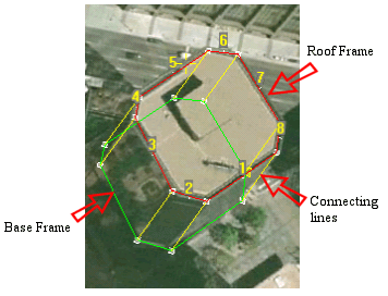
3. In the 3D Window, select the angular roof points and drag them to the top-most position of the roof. The angular roof points are located between the connecting lines (cyan) and the rooftop frame (purple). The points of the angular roof shape should not overlap each other.
Note: For adding additional angular roof points, you must switch to Edit Nodes mode, add additional roof point in the desired location and switch back to Edit Angular Roof mode.
4. In the Geometry section of the property sheet, set the rooftop delta height.
Angular Roof Geometry Setting
Working with the Building Lean Ratio Parameters
In many cases, the aerial imagery in large parts of a city has the same pitch angle. This means that all the buildings in this area have the same leaning ratio on the imagery. After manually setting one building, you can select all the buildings in this area and set the Building Lean X Ratio and Building Lean Y Ratio parameters according to the values of the building you have set manually.
TerraExplorer automatically calculates the roof and base locations according to the buildings’ height and the leaning ratio you have set. The calculation is valid only when the rooftop frames are located in the correct geographic location and not according to the distorted imagery.
Note: This feature is mostly relevant when loading the rooftop geometry from an external feature layer.
Building Property Sheet Parameters
|
Object Parameter |
Activity |
|
Appearance |
|
|
Name |
Type the description or name of the building. This text appears in the Project Tree as the name of the object. |
|
Activation Action |
Select the action to perform when selecting the building from the Project Tree. |
|
Rooftop Style |
Determines whether the roof is flat or angular |
|
Position |
|
|
Altitude Method |
Sets the altitude method to be used by the building: § Select Relative to Terrain to set the building’s altitude values at a specified altitude above the ground. § Select Absolute to set the building’s altitude values at a specified altitude above the terrain database vertical datum base ellipsoid. |
|
Base Altitude |
Enter the altitude, as defined in Altitude Method, for the base of the building. |
|
Roof Altitude |
Enter the altitude, as defined in Altitude Method, for the roof of the building. |
|
X |
Enter the X coordinate for the building’s pivot point, the center of its base. |
|
Y |
Enter the Y coordinate for the building’s pivot point, the center of its base. |
|
Geometry |
|
|
Building Height |
Determines the height of the building above its base. This is identical to the difference between the Roof Altitude and Base Altitude. |
|
Rooftop Delta Height |
Determines the height of the top of the angular roof above the building. This field is available only when Rooftop Style is set to Angular roof. |
|
Texture Note: These fields are unavailable if you have selected the Stretch Terrain style. |
|
|
Selected Face |
Select the face to modify. § Roof: Select this option to change the roof color or texture. § All Walls: Select this option to change the color or texture for all walls in the building. § Wall #: Select a single wall to edit. Note: The walls are numbered according to the creation order. You can view the numbering labels above the center of the roof segment for each wall.
|
|
Face Fill Type |
Select the fill type of the selected face. § Single Color: The face gets a single color filling according to the Face Color field. § Image File Texture: The face gets the texture from an external texture file according to the Face Texture File field. Note: Building texture files can be loaded from the Buildings-Textures folder located under the TE application files ((.\Program Files\Skyline\TerraExplorer Pro\Tools\Data-Library\Buildings-Textures) and old projects using these textures will be supported. § Terrain Texture: The face gets the texture from the terrain imagery according to the Face Terrain Texture field. |
|
Face Color |
Select the color of the selected face. Click the Edit button to open the Color dialog, or type the color code in hexadecimal BBGGRR format (B = Blue channel 00-ff, G = Green channel 00-ff, R = Red channel 00-ff). |
|
Face Texture File |
Type the full path of the file, or use the Edit button, for a BMP, GIF or JPEG texture file to provide the texture for the selected face. Note: The faces texture dimensions must be a power of 2 (i.e., 32 pixels by 64 pixels). Note: You can set a transparent color for GIF and BMP files. Pixels with this color appear as holes in the building. With GIF files, you can assign any color as the transparent color by using the GIF transparent color feature. With BMP files, the total-black color (RGB = 0, 0, 0) is used as the transparent color. |
|
Face Terrain Texture |
Assign a terrain texture to the selected face. The Face Terrain Texture dropdown list displays all the walls of the building with exposed texture. By default, every exposed wall gets its own texture and all other walls get the biggest exposed texture. You can override this setting by assigning any exposed texture to any wall of the building. Note: This field is available only if Terrain Texture option is selected. |
|
Face Tiling Method |
Determines the type of scaling for the texture. Note: The Face Tiling Method, Face Scale X, Face Scale Y and Face Rotation parameters are available only for faces with “Image File Texture” fill type. |
|
Face Scale X |
Determines the scaling for the texture according to the setting for Tiling Method: § If the Tiling Method is Tiles per face: It determines the number of repeats, for the selected face, of the texture in the X-axis. § If the Tiling Method is Meters per Tile: It determines the size of each texture tile in meters in the X-axis. If the texture is smaller than the face, it repeated until it fills the face. |
|
Face Scale Y |
Determines the scaling for the texture according to the setting for Tiling Method: § If the Tiling Method is Tiles per face: It determines the number of repeats, for the selected face, of the texture in the Y-axis. § If the Tiling Method is Meters per Tile: It determines the size of each texture tile in meters in the Y-axis. If the texture is smaller than the face, it repeated until it fills the face. |
|
Face Rotation |
Determines the angular rotation of the texture used for the selected face. |
|
Building Lean X Ratio |
The offset in the X-axis between the roof position, in the image, and the actual building position, divided by the building height. |
|
Building Lean Y Ratio |
The offset in the Y-axis between the roof position, in the image, and the actual building position, divided by the building height. |
|
Timespan |
|
|
Start Time |
Click Edit and select the date and time when the building should first become visible. |
|
End Time |
Click Edit and select the date and time when the building should stop being visible. |
|
Visibility |
|
|
Default Viewing Distance |
Determines the viewing distance of the building from the polyline. This distance is used as a stop mark for any “Fly-to” or “View Object” operation. It is also used when selecting to edit the object from the Project Tree. When this value is set to the default of -1, TerraExplorer calculates and sets the ideal viewing distance for the building based on its size. |
|
Max. Visibility Distance |
Sets the maximal distance from the camera above which the building disappears. |
|
Min. Visibility Distance |
Sets the minimal distance from the camera below which the building disappears. |
|
General |
|
|
Show in Viewer |
Determines if the building appears in the Project Tree when the file is viewed with the TerraExplorer Basic Viewer. |
|
Message |
The message associated with the object. The number displayed is the number of the message. To create a new message, or update an existing message, open the Create Message dialog by clicking in this field and selecting Edit. See “Using the Create Message Dialog” in the “Working with Objects” chapter for more information. |
|
Tooltip |
Type a tooltip text to appear when the mouse cursor is placed over the building in the 3D Window. |
|
Ground Object |
Determines if the object is calculated as part of the terrain’s elevation. |