Modifying LiDAR Properties
LiDAR data can be viewed and modified in the LiDARs list and point cloud properties dialog. This dialog is accessed from a right-click menu as described below.
To display and modify LiDAR point cloud properties:
1. In the Project Tree select the LiDARs group, and then in the LiDARs list, select the required LiDAR.
2. For basic properties such as path and coordinate system, in the LiDARs list, select the check boxes of the required LiDARs, and modify their properties as required. See "LiDARs List" in this chapter for more information.
Note: You can also search the list for the required LiDAR. See "Selecting Items Using the Item List" in the "Basic Concepts" chapter for information.
3. For point styling properties and other properties relating to how the point cloud is displayed, right-click the required LiDAR, and select Style Point Cloud. The Point Cloud Properties dialog is displayed. See "LiDAR Point Cloud Properties Dialog" in this chapter for more information.
Note: A LiDAR must be converted to CPT, PhotoMesh's internal format before it can be styled. You can convert the LiDAR by performing the build's data preparation step or by Showing Point Cloud. See "About Building" in the "Building" chapter and "Showing a LiDAR Point Cloud on the Terrain" in this chapter for more information.
LiDAR Point Cloud Properties Dialog
Property |
Description |
|
Style |
||
Point Size |
Size, in pixels, of each of the LiDAR
point cloud’s points. If you want to base the point size on attribute
fields, click the Field by Attribute button |
|
Point Color |
Color of the LiDAR point cloud points. This can be set to either of the following: § A set color value for all the points. To select a color, click Edit and select a color. § Based on
a specific attribute field - To base each point of the point cloud’s
color on a specific attribute field’s value, click the Field
by Attribute button |
|
Point Visibility |
Determines if the LiDAR point cloud’s
points are visible. To set the visibility of points based on their
attribute values, click the Field by Attribute button |
|
Intensity Blend |
Determines how much the LiDAR point cloud’s intensity value is factored in colorizing the point cloud, where 0% colorizes the point cloud model by point color only, and 100% colorizes by intensity only. |
|
Oversampling |
The LiDAR point cloud’s Level of Detail (LOD). When set to Normal, PhotoMesh determines the optimal quality to performance balance based on the current view. The "High" and "Best" settings will load more points but are also more resource-intensive. |
|
Flatten Underlying Terrain |
Determines if the terrain under the model is leveled to the model’s elevation value. This option is enabled only if the Altitude Method property in the point cloud property sheet is set to Absolute. |
|
Hide Underlying Terrain |
Hides the terrain texture under the LiDAR point cloud model (the terrain appears as a black image). |
|
LiDARs List
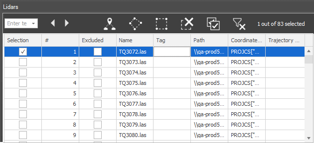
In the LiDARs list, you can view and set the LiDAR’s coordinate system, path and trajectory path, as well as set LiDAR visibility and inclusion in the project. See "About the Item List" in the "Using the Project Tree and Item List" chapter for information on working with the LiDARs list.

LiDARs List
To open the LiDARs list:
In the Project Tree, select the LiDARs group. The LiDARs list is displayed with a list of all the LiDAR files in the project, and the following information:
Property |
Description |
Selection |
Select the check box to select the LiDAR in the 3D Window. |
# |
Number of the LiDAR. |
Name |
Name of LiDAR file. |
Excluded |
Select the check box to exclude the LiDAR point cloud from the project. |
Box |
Select the check box to show the LiDAR's bounding box. |
Point Cloud |
Select the check box to show a LiDAR point cloud on the terrain. |
Coordinate System |
Coordinate system of the LiDAR point cloud.
Click Select |
Path |
Full path to the LiDAR point cloud. |
Trajectory Path |
Full path to file that provides information about the scanner’s position while capturing the point cloud. See "Associating a LiDAR Point Cloud with its Trajectory Data" in this chapter for more information on trajectory files. |
Tag |
Free text about the LiDAR |